Chrysler Town & Country/Voyager, Dodge Caravan, Plymouth Voyager. Manual - part 317


  Index      Chrysler     Chrysler Town & Country/Voyager, Dodge Caravan, Plymouth Voyager - service repair manual 1992 year


Search            


Content   ..  315  316  317  318   ..


Chrysler Town & Country/Voyager, Dodge Caravan, Plymouth Voyager. Manual - part 317


CYLINDER BLOCK, PISTON AND CONNECTING
ROD ASSEMBLY SERVICE

CYLINDER BLOCK

PISTON—REMOVAL

(1) Remove top ridge of cylinder bores with a reliable

ridge reamer before removing pistons from cylinder
block. Be sure to keep tops of pistons covered
during this operation. Pistons and connecting
rods must be removed from top of cylinder block.
When removing piston and connecting rod as-
semblies from the engine, rotate crankshaft so
that each connecting rod is centered in cylinder
bore.

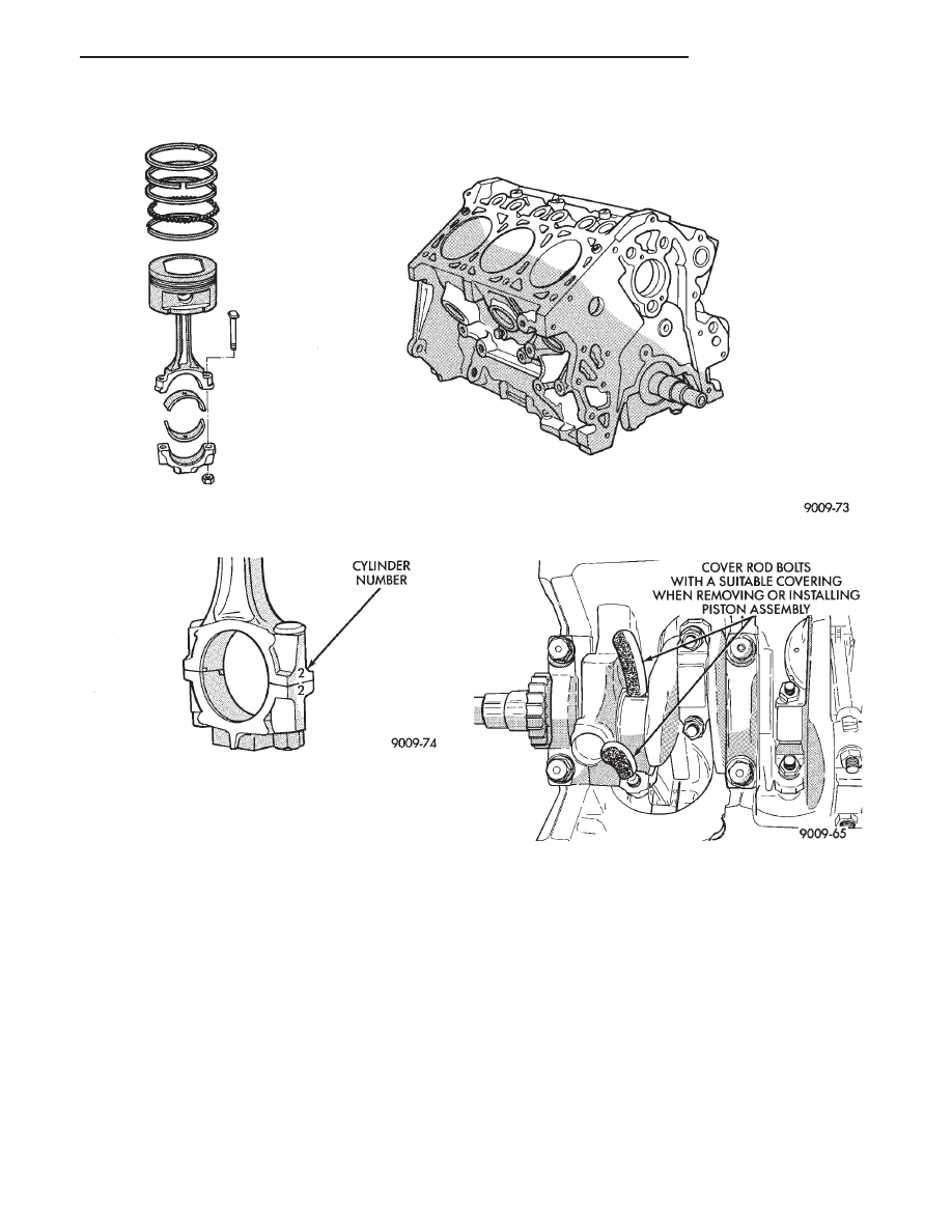
(2) Inspect connecting rods and connecting rod caps

for cylinder identification. Identify them if necessary.
(Fig. 2)

(3) Remove connecting rod cap. Install connecting

rod bolt protectors on connecting rod bolts (Fig. 3).
Push each piston and rod assembly out of cylinder bore.

Be careful not to nick crankshaft journals.

(4) After removal, install bearing cap on the mating
rod.

CLEANING AND INSPECTION

(1) Clean cylinder block thoroughly and check all

core hole plugs for evidence of leaking.

(2) If new core plugs are installed, see Engine Core

Oil and Cam Plugs.

(3) Examine block for cracks or fractures.

CYLINDER BORE INSPECTION

The cylinder walls should be checked for out- of-

round and taper with Tool C-119 (Fig. 4). If the cylinder
walls are badly scuffed or scored, the cylinder block
should be rebored and honed, and new pistons

Fig. 1 Cylinder Block, Piston and Connecting Rod Assembly

Fig. 2 Identify Connecting Rod to Cylinder

Fig. 3 Connecting Rod Protectors

.

3.3L ENGINE

9 - 99

and rings fitted. Whatever type of boring equipment is
used, boring and honing operation should be closely
coordinated with the fitting of pistons and rings in
order that specified clearances may be maintained.

Refer to Honing Cylinder Bores outlined in the

Standard Service Procedures for specification
and procedures.

Measure the cylinder bore at three levels in direc-

tions A and B (Fig. 4). Top measurement should be
12mm (.50 inch) down and bottom measurement
should be 12mm (.50 inch.) up from bottom of bore.
Refer to (Fig. 5) for specifications.

FINISHED PISTONS

All pistons are machined to the same weight in

grams, regardless of oversize, to maintain piston bal-
ance.

FITTING PISTONS

Piston and cylinder wall must be clean and dry.

Piston diameter should be measured 90 degrees to
piston pin at size location shown in (Fig. 6). Cylinder
bores should be measured halfway down the cylinder
bore and transverse to the engine crankshaft center
line shown in (Fig. 4). Refer to (Fig. 5) for specifica-
tions.

Pistons and cylinder bores should be measured

at normal room temperature, 70°F. (21°C).

PISTON PINS

The piston pin rotates in the piston only, and is

retained by the press interference fit of the piston pin
in the connecting rod. The piston pin is not to be
removed damage to the piston may result.

FITTING RINGS

(1) Wipe cylinder bore clean. Insert ring and push

down with piston to ensure it is square in bore. The
ring gap measurement must be made with the ring
positioning at least 12mm (.50 inch) from bottom of
cylinder bore. Check gap with feeler gauge (Fig. 7).

Refer to specifications (Fig. 8).
(2) Check piston ring to groove clearance: (Fig. 9).

Refer to specification (Fig. 8).

PISTON RINGS—INSTALLATION

(1) The No. 1 and No. 2 piston rings have a different

cross section. Install rings with manufacturers I.D.
mark facing up, to the top of the piston (Fig. 10).

Fig. 4 Checking Cylinder Bore Size

Fig. 5 Cylinder Bore and Piston Specifications

Fig. 6 Piston Measurements

Fig. 7 Check Gap on Piston Rings

9 - 100

3.3L ENGINE

.

CAUTION: Install piston rings in the following order:

(a) Oil ring expander.
(b) Upper oil ring side rail.
(c) Lower oil ring side rail.
(d) No. 2 Intermediate piston ring.
(e) No. 1 Upper piston ring.

(2) Install the side rail by placing one end between

the piston ring groove and the expander. Hold end
firmly and press down the portion to be installed until
side rail is in position. Do not use a piston ring
expander. 
(Fig. 11).

(3) Install upper side rail first and then the lower

side rail.

(4) Install No. 2 piston ring and then No. 1 piston

ring (Fig. 12).

(5) Position piston ring end gaps as shown in (Fig.

13).

(6) Position oil ring expander gap at least 45° from

the side rail gaps but not on the piston pin center or on
the thrust direction. Staggering ring gap is important
for oil control.

Fig. 8 Piston Ring Specifications

Fig. 9 Measuring Piston Ring Side Clearance

Fig. 10 Piston Ring Installation

Fig. 11 Installing Side Rail

Fig. 12 Installing Upper and Intermediate Rings

.

3.3L ENGINE

9 - 101

INSTALLING PISTON AND CONNECTING ROD AS-
SEMBLY

(1) Before installing pistons, and connecting rod

assemblies into the bore, besure that compression ring
gaps are staggered so that neither is in line with oil
ring rail gap.

(2) Before installing the ring compressor, make sure

the oil ring expander ends are butted and the rail gaps
located as shown in (Fig. 14).

(3) Immerse the piston head and rings in clean

engine oil, slide the ring compressor, over the piston
and tighten with the special wrench. Be sure position
of rings does not change during this operation.

(4) Install connecting rod bolt protectors on rod

bolts. (Fig. 3)

(5) Rotate crankshaft so that the connecting rod

journal is on the center of the cylinder bore. Insert rod
and piston into cylinder bore and guide rod over the
crankshaft journal.

(6) Tap the piston down in cylinder bore, using a

hammer handle. At the same time, guide connecting
rod into position on connecting rod journal.

(7) The notch or groove on top of piston must be

pointing toward front of engine (Fig. 15).

(8) Install rod caps. Install nuts on cleaned and oiled

rod bolts and tighten nuts to 54 N

Im (40 ft. lb.) Plus 1/4

turn.

Fig. 13 Piston Ring End Gap Position

Fig. 14 Installing Piston

Fig. 15 Piston I.D. Notches

Fig. 16 Checking Connecting Rod Bearing Clear-

ance

9 - 102

3.3L ENGINE

.


Content   ..  315  316  317  318   ..