Chrysler Town & Country/Voyager, Dodge Caravan, Plymouth Voyager. Manual - part 307


  Index      Chrysler     Chrysler Town & Country/Voyager, Dodge Caravan, Plymouth Voyager - service repair manual 1992 year


Search            


Content   ..  305  306  307  308   ..


Chrysler Town & Country/Voyager, Dodge Caravan, Plymouth Voyager. Manual - part 307


CYLINDER HEAD AND CAMSHAFT SERVICE

CYLINDER HEAD COVER

REMOVAL

(1) Remove air cleaner assembly.
(2) Disconnect battery and relocate spark plug

wires.

(3) Remove vacuum connections.
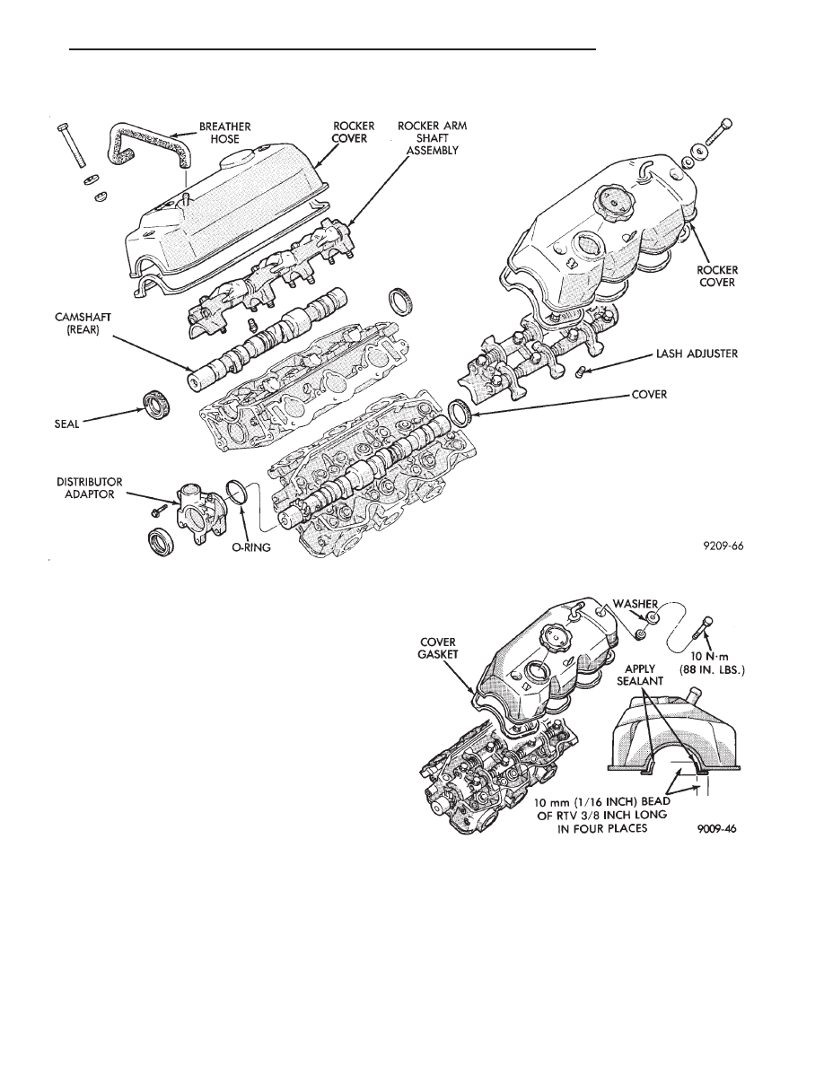
(4) Remove rocker cover screws and remove cover

(Fig. 2).

INSTALLATION

(1) Clean cylinder head and cover mating surfaces.

Install new gasket.

(2) See (Fig. 2) and apply sealant such as Mopar

Silicone Rubber Adhesive Sealant to cover ends.

(3) Install cover and tighten cover bolt washer and

gasket assembly to 10 N

Im (88 in. lbs.).

AUTO LASH ADJUSTER

The automatic lash adjusters are precision units

installed in machined openings in the valve actuating
ends of the rocker arms. Do not disassemble the auto
lash adjuster.

FUNCTION CHECK

Check auto adjusters for free play by inserting a

small wire through the air bleed hole in the rocker arm
and VERY LIGHTLY push the auto adjuster ball
check down (Fig. 3). While lightly holding the check
ball down move the rocker up and down to check for
free play. If there is no play replace the adjuster.

Fig. 1 Cylinder Head-Camshaft-Valves

Fig. 2 Rocker Cover

.

3.0L ENGINE

9 - 59

CAMSHAFT SERVICE

SEE AUTO LASH ADJUSTER FUNCTION
CHECK BEFORE DISASSEMBLY

REMOVAL

(1) Install auto lash adjuster retainers. (Fig. 4).
(2) Remove distributor extension (Fig. 1).
(3) When removing camshaft bearing caps do not

remove the bolts from the bearing caps. Remove the
rocker arm, rocker shafts and bearing cap as an
assembly.

CAMSHAFT INSPECTION

(1) Inspect camshaft bearing journals for damage

and binding (Fig. 5). If journals are binding,also check
the cylinder head for damage (Fig. 1). Also check
cylinder head oil holes for clogging.

(2) Front cylinder head camshaft check the tooth

surface of the distributor drive gear teeth of the cam-
shaft and replace if abnormal wear is evident (Fig. 5).

(3) Check the cam surface for abnormal wear and

damage and replace if defective. Also measure the cam
height (Fig. 5) and replace if out of limit, standard
value is 41.25 mm (1.624 inch), wear limit is 40.75 mm
(1.604 inch).

CAMSHAFT INSTALL

Lubricate camshaft journals and cams with engine

oil and install camshaft on cylinder head.

ROCKER ARMS

(1) Check rocker arms for wear or damage (Fig. 6).

Replace as necessary. Also see Auto Lash Adjuster.

ROCKER ARM SHAFTS

The rocker arm shaft is hollow and is used as a

lubrication oil duct. The rocker arm shaft on the inlet

Fig. 3 Auto Lash Adjuster Check

Fig. 4 Auto Lash Adjuster Retainers

Fig. 5 Check Camshafts

Fig. 6 Inspect Rocker Arms

9 - 60

3.0L ENGINE

.

side has a 3mm diameter oil passage hole from the
cylinder head. The exhaust side does not have this oil
passage (Fig. 7).

(1) Check the rocker arm mounting portion of the

shafts for wear or damage. Replace if heavily damaged
or worn.

(2) Check oil holes for clogging with small wire,

clean as required (Fig. 7).

REASSEMBLE

(1) Align the camshaft bearing caps with arrows

(depending on cylinder bank) directed as shown in (Fig.
8) and in numerical order.

Identify number one bearing cap number one and

number four caps are similar (Fig. 9).

(2) Install rocker shafts into bearing cap number one

with end notches positioned as shown in (Fig. 9) that
the machined portion of the rocker shaft is facing
down.

(3) Insert attaching bolts to retain assembly.

ASSEMBLE ROCKER ASSEMBLY

Install the rocker arms, bearing caps and springs.

Springs are the same and can be used at all
locations 
on the rocker arm shafts (Figs. 8 and 10).
Insert bolts in number four bearing cap to retain
assembly.

INSTALL ROCKER ARM SHAFT ASSEMBLY

(1) Apply Mopar Silicone Rubber Adhesive Sealant

at bearing cap ends as shown in (Fig. 8).

(2) Install the rocker arm shaft assembly making

sure that the arrow mark on the bearing cap and the
arrow mark on the cylinder head are in the same
direction (Fig. 8).

The direction of arrow marks on the front and

rear assemblies are opposite to each other.

(3) Tighten bearing cap bolts in the following order

to 10 N

Im (85 in. lbs.). First #3, then #2, #1 and #4.

(4) Repeat step 3 increasing the torque to 20 N

Im

(180 in.lbs.).

(5) Install distributor drive adaptor assembly (Fig.

11).

CAMSHAFT OIL SEAL — ENGINE OUT OF VE-
HICLE

(1) Apply light coat of engine oil to the camshaft oil

seal lip.

(2) Install the oil seal using camshaft oil seal in-

staller tool MD998713 (Fig. 12).

CAMSHAFT END SEAL (PLUG) — ENGINE IN
VEHICLE

(1) Remove air cleaner assembly from engine.
(2) Use a small punch and a hammer, carefully

remove cam plug from cylinder head.

(3) Clean the area of the cylinder head where the

new cam plug will be installed.

(4) Apply a light coating of Mopar Silicone Rubber

Adhesive Sealant to the outer diameter of the NEW
cam plug.

(5) Using a suitable installing tool and a hammer,

Fig. 7 Rocker Arm Shaft Identification

Fig. 8 Camshaft Bearing Caps Position

Fig. 9 Number One Camshaft Bearing Cap

.

3.0L ENGINE

9 - 61

install the new cam plug to a depth of 0.5mm (0.020
inch) below the surface of the cylinder head.

(6) Replace air cleaner assembly.

CAMSHAFT END SEAL (PLUG) — ENGINE OUT
OF VEHICLE

Install end seal plug with Special Tool MD998306.

(Fig. 13).

CYLINDER HEAD

REMOVAL

(1) See Timing System this group for disassembly

and remove camshaft sprockets.

Fig. 10 Assemble Rocker Arm and Shafts

Fig. 11 Distributor Drive

Fig. 12 Install Camshaft Oil Seal

9 - 62

3.0L ENGINE

.


Content   ..  305  306  307  308   ..