Chrysler Town & Country/Voyager, Dodge Caravan, Plymouth Voyager. Manual - part 306


  Index      Chrysler     Chrysler Town & Country/Voyager, Dodge Caravan, Plymouth Voyager - service repair manual 1992 year


Search            


Content   ..  304  305  306  307   ..


Chrysler Town & Country/Voyager, Dodge Caravan, Plymouth Voyager. Manual - part 306


(3) Inspect drive belt for wear and damage (Fig. 5).
(4) Installation: Adjust belt tension to 5/16 deflection

between pulleys (Fig. 6).

(5) Install breaker bar into 1/2 square opening in

tensioner.

(6) Rotate tensioner counterclockwise to remove and

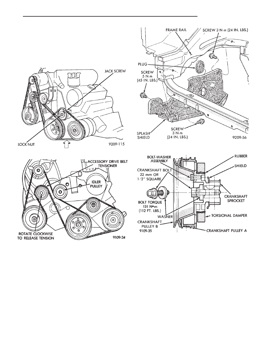
install belt (Fig. 7).

ENGINE MOUNT BRACKET

REMOVAL

(1) Remove air conditioning compressor to mounting

bracket screws and lay compressor aside (Fig. 4).

(2) Remove screws attaching air conditioning com-

pressor mounting bracket and adjustable drive belt
tensioner from block and engine mounting bracket.
Remove both assemblies.

(3) Remove steering pump/alternator belt tensioner

mounting bolt and remove automatic belt tensioner.

(4) Remove two steering pump to engine mounting

bracket screws and one rear support lock nut.

(5) Lay power steering pump aside.
(6) Raise vehicle and remove right inner splash

shield (Fig. 8).

(7) Remove crankshaft drive pulleys and torsional

damper (Fig. 9).

(8) Lower vehicle and place a jack under engine.
(9) Separate engine mount insulator from engine

mount bracket (Fig. 10). Raise engine slightly.

(10) Remove engine mount bracket (Fig. 10).
(11) Remove timing belt covers (Fig. 11).

TIMING BELT INSPECTION—IN VEHICLE

(1) Remove the upper front outer timing belt cover

by loosening the three attaching bolts. (Fig. 11).

(2) Inspect both sides of the timing belt drive & back.

Replace belt if any of the following conditions exist.
• Hardening of back rubber back side is glossy with-
out resilience and leaves no indent when pressed with
fingernail.

Fig. 6 Air Conditioning Belt

Fig. 7 Alternator/Power Steering Belt

Fig. 8 Right Inner Splash Shield—Typical

Fig. 9 Crankshaft Drive Pulleys

.

3.0L ENGINE

9 - 55

• Cracks on rubber back.

• Cracks or peeling of canvas.

• Cracks on rib root.

• Cracks on belt sides.

• Missing teeth.

• Abnormal wear of belt sides. The sides are normal if
they are sharp as if cut by a knife (Fig. 12).

(3) If none of the above conditions are seen on the

belt, the belt cover can be reinstalled.

TIMING BELT SERVICE

REMOVAL

(1) Mark belt running direction for installation (Fig.

14).

(2) Loosen timing belt tensioner bolt (Fig. 16) and

remove timing belt.

(3) Remove crankshaft sprocket flange shield (Fig.

9).

CAMSHAFT SPROCKETS

REMOVAL

(1) Hold camshaft sprocket with Spanner Tool

MB990775 loosen and remove bolt and washer (Fig.
15).

(2) Remove camshaft sprocket from camshaft.

INSTALLATION

(1) Place camshaft sprocket on camshaft.
(2) Install bolt and washer to camshaft. Using Span-

ner Tool MB990775 hold camshaft sprocket and torque
bolt to 95 N

Im (70 ft. lbs.) (Fig. 15).

TIMING BELT TENSIONER

(1) Install timing belt tensioner and tensioner

spring.

(2) Hook spring upper end to water pump pin and

lower end to tensioner bracket with hook out (Fig. 16).

(3) Turn timing belt tensioner counter-clockwise full

travel in adjustment slot and tighten bolt to tempo-
rarily hold this position (Fig. 17).

Fig. 10 Right Engine Mount and

Engine Mount Bracket

Fig. 11 Timing Belt Covers

Fig. 12 Timing Belt Inspection

9 - 56

3.0L ENGINE

.

Fig. 13 Timing Belt System

Fig. 14 Timing Belt EFngine Sprocket Timing

.

3.0L ENGINE

9 - 57

INSTALLATION—TIMING BELT

(1) Install timing belt on crankshaft sprocket first

and while keeping belt tight on tension side (Fig. 14)
install belt on the front (radiator side) camshaft
sprocket.

(2) Then, install on the water pump pulley and on

the rear camshaft sprocket and finally on the timing
belt tensioner.

(3) Apply rotating force to the front camshaft

sprocket in opposite direction to tension the belt ten-
sion side and check that all timing marks are lined up
(Fig. 14).

(4) Install crankshaft sprocket flange (Fig. 13).
(5) Loosen tensioner bolt and allow spring to tension

timing belt.

(6) Turn crankshaft two full turns in clockwise di-

rection. Turn smoothly and in clockwise direction
ONLY.

(7) Again line up the timing marks on the sprockets

and tighten the timing belt tensioner locking bolt to 25
N

Im (250 in. lbs.) torque.

(8) Reassembly belt covers, engine Bracket, Insula-

tor, crankshaft pulleys, accessories and accessory drive
belts in reverse order.

Fig. 15 Camshaft Sprockets

Fig. 16 Timing Belt Tensioner

Fig. 17 Positioning Belt Tensioner

9 - 58

3.0L ENGINE

.


Content   ..  304  305  306  307   ..