Chrysler Town & Country/Voyager, Dodge Caravan, Plymouth Voyager. Manual - part 308


  Index      Chrysler     Chrysler Town & Country/Voyager, Dodge Caravan, Plymouth Voyager - service repair manual 1992 year


Search            


Content   ..  306  307  308  309   ..


Chrysler Town & Country/Voyager, Dodge Caravan, Plymouth Voyager. Manual - part 308


(2) See Camshaft Rocker Arms Removal.
(3) Remove upper intake manifold assembly. Refer

to Intake and Exhaust Manifolds, Group 11.

(4) Remove distributor.
(5) Remove exhaust manifolds and cross over Refer

to Intake and Exhaust Manifolds, Group 11.

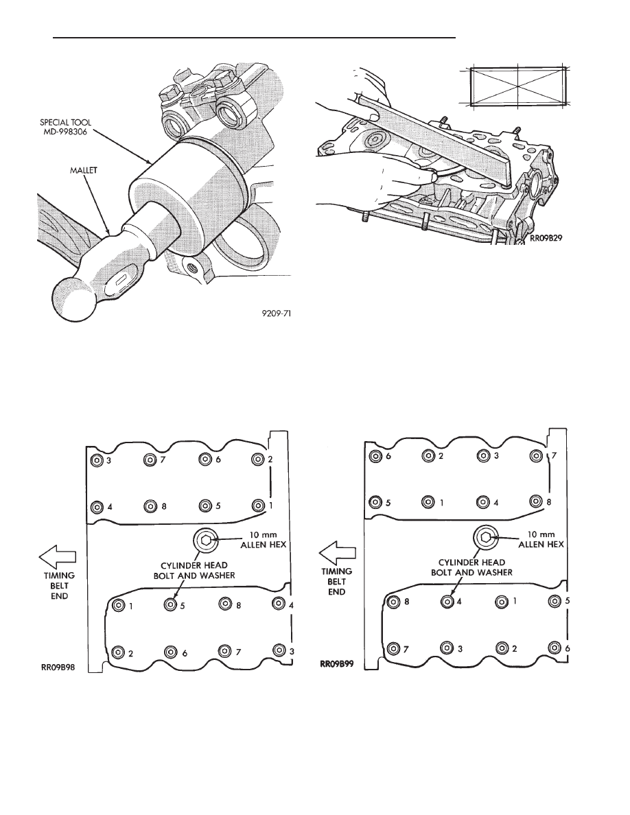
(6) Remove cylinder head bolts in sequence shown

in (Fig. 14) and remove cylinder head.

INSPECTION

(1) Before cleaning, check for leaks, damage and

cracks.

(2) Clean cylinder head and oil passages.
(3) Check cylinder head for flatness (Fig. 15).
(4) Cylinder head must be flat within;

• Standard dimension = less than 0.05mm (.002
inch)
• Service Limit = 0.2mm (.008 inch)

• Grinding Limit = Maximum of 0.2 mm (.008 inch)
is permitted.

CAUTION: This is a combined total dimension of
stock removal from cylinder head if any and block
top surface.

INSTALLATION

(1) Clean surfaces of head and block, install head

gasket over locating dowels.

(2) Install head on locating dowels.
(3) Install 10mm Allen Hex head bolts with wash-

ers.

Fig. 13 Install Camshaft End Seal—Plug

Fig. 14 Cylinder Head Bolt Removal Sequence

Fig. 15 Check Cylinder Head

Fig. 16 Cylinder Head Bolt Tightening Sequence

.

3.0L ENGINE

9 - 63

(4) Tighten bolts in the order shown in (Fig. 16).

When tightening the cylinder head bolts, tighten
gradually, working in two or three steps and finally
tighten to specified torque of 108 N

Im (80 ft. lbs.).

VALVE SERVICE

VALVE AND VALVE SPRINGS

(1) With suitable valve spring compressor, remove

spring retainer locks, retainer, valve spring, spring
seat and valve (Fig. 17).

(2) Remove valve stem seals with suitable tool (Fig.

18). Do not reuse valve stem seals.

VALVES

(1) Check valve stem tip for pitting or depression at

point A (Fig. 19).

(2) Check for wear and ridge wear at Point B.
(3) Check for even contact (at face center) with valve

seat, Point C.

(4) Check margin. Replace valve if margin is out of

specification (Fig. 20).

(5) Measure valve stem to guide clearance.

(6) Measure Valve spring free length and squareness

(Fig. 21). Refer to (Fig. 20) for specifications.

VALVE SEAT INSPECTION

Inspect the valve seat with Prussian blue to deter-

mine where the valve contacts the seat. To do this,

Fig. 17 Remove Valves

Fig. 18 Remove Valve Stem Seals

Fig. 19 Valve Inspection

Fig. 20 Valve Specification

Fig. 21 Valve Spring

9 - 64

3.0L ENGINE

.

coat valve seat LIGHTLY with Prussian blue then set
valve in place. Rotate the valve with light pressure. If
the blue is transferred to the center of valve face,
contact is satisfactory. If the blue is transferred to top
edge of the valve face, lower valve seat with a 15
degrees stone. If the blue is transferred to the bottom
edge of valve face raise valve seat with a 65 degree
stone.

(1) Install valve spring seat.
(2) Using suitable tool install seal by tapping lightly

until seal is in place. (Fig. 23).

(3) Install valve spring with the enamelled ends

facing the rocker arms (Fig. 24).

CAUTION: During reassembly, compressing the valve
spring more than necessary to install valve spring
retainer locks can cause the retainer to be forced
against the stem seal and damaging it.

Fig. 24 Installed Valve Spring Position

Fig. 22 Valve Seat Reconditioning

Fig. 23 Install Valve Stem Seals

.

3.0L ENGINE

9 - 65

PISTON AND CONNECTING ROD ASSEMBLY SER-
VICE

(1) Mark Identify Pistons.The pistons are not in-

terchangeable from bank to bank (Fig. 2).

(2) Mark connecting rod and cap with cylinder num-

ber (Fig. 3).

(3) Remove piston rings (Fig. 4).

CYLINDER BORE INSPECTION

(1) Measure the cylinder bore at three levels in

directions A and B (Fig. 5). Top measurement should be
12mm (.50 inch) down and bottom measurement
should be 10mm (.38 inch) up.

(2) Standard bore dimension: 91.1mm (3.587 inch)
(3) Maximum out-of-round or taper: 0.02mm (.0008

inch)

FITTING PISTONS

Measure approximately 2mm (.080 inch) above the

bottom of the piston skirt and across the thrust face.
(Fig. 6), See Boring Cylinder in Cylinder Block.

FITTING PISTON RINGS

(1) Wipe cylinder bore clean. Insert ring and push

down with piston to ensure it is square in bore. The
ring gap measurement must be made with the ring
positioning at least 16mm (0.63 inch) from bottom of
cylinder bore. Check gap with feeler gauge (Fig. 7).
Refer to (Fig. 8) for specification.

(2) Check piston ring to groove clearance; Refer to

Piston Ring Specification Chart (Fig. 8).

Fig. 1 Pistons, Connecting Rods

Fig. 2 Mark Pistons

Fig. 3 Mark Matching Parts

9 - 66

3.0L ENGINE

.


Content   ..  306  307  308  309   ..