Chrysler Town & Country/Voyager, Dodge Caravan, Plymouth Voyager. Manual - part 301


  Index      Chrysler     Chrysler Town & Country/Voyager, Dodge Caravan, Plymouth Voyager - service repair manual 1992 year


Search            


Content   ..  299  300  301  302   ..


Chrysler Town & Country/Voyager, Dodge Caravan, Plymouth Voyager. Manual - part 301


CRANKSHAFT SERVICE

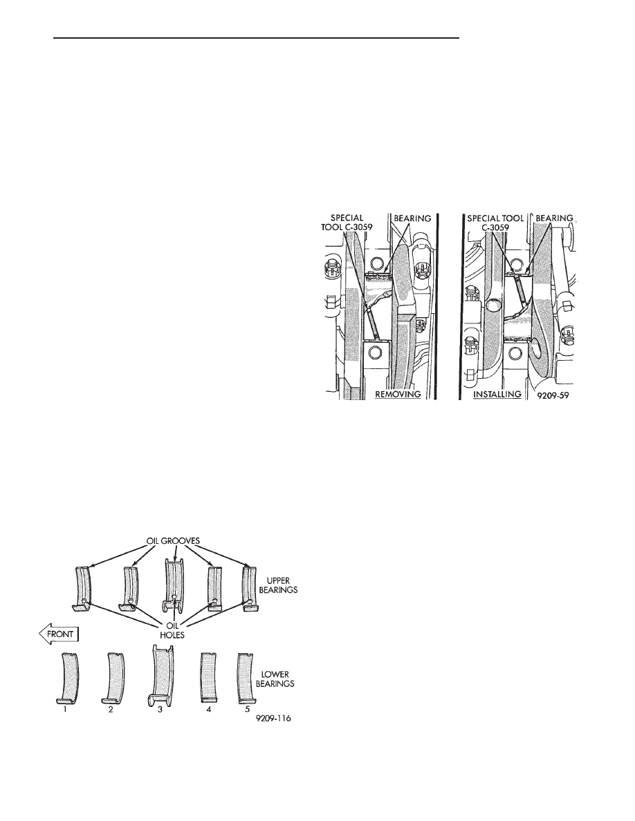
CRANKSHAFT MAIN BEARINGS

Bearing caps are not interchangeable and should be

marked at removal to insure correct assembly. Upper
and lower bearing halves are NOT interchangeable.
Lower main bearing halves of 1, 2, 4 and 5 are
interchangeable. Upper main bearing halves of 1, 2, 4
and 5 are interchangeable.

CRANKSHAFT MAIN JOURNALS

The crankshaft journals should be checked for exces-

sive wear, taper and scoring. (Fig. 7) Limits of taper or
out-of-round on any crankshaft journals should be held
to .025mm (.001 inch). Journal grinding should not
exceed .305mm (.012 inch) under the standard journal
diameter. Do NOT grind thrust faces of Number 3 main
bearing. Do NOT nick crank pin or bearing fillets. After
grinding, remove rough edges from crankshaft oil holes
and clean out all passages.

CAUTION: With the nodular cast iron crankshafts
used it is important that the final paper or cloth polish
after any journal regrind be in the same direction as
normal rotation in the engine.

Upper and lower Number 3 bearing halves are

flanged to carry the crankshaft thrust loads and are
NOT interchangeable with any other bearing halves in
the engine (Fig. 7). All bearing cap bolts removed
during service procedures are to be cleaned and oiled
before installation. Bearing shells are available in
standard and the following undersized: 0.025mm (.001
inch), .051mm (.002 inch), .076mm (.003 inch), .254mm
(.010 inch), and .305mm (.012 inch). Never install an
undersize bearing that will reduce clearance below
specifications.

MAIN BEARING SERVICE—CRANKSHAFT NOT
REMOVED

REMOVAL

(1) Remove oil pan and identify bearing caps before

removal.

(2) Remove bearing caps one at a time. Remove

upper half of bearing by inserting Special Main Bear-
ing Tool C-3059 (Fig. 8) into the oil hole of crankshaft.

(3) Slowly rotate crankshaft clockwise, forcing out

upper half of bearing shell.

INSTALLATION

Only one main bearing should be selectively

fitted while all other main bearing caps are prop-
erly tightened.

When installing a new upper bearing shell, slightly

chamfer the sharp edges from the plain side.

(1) Start bearing in place, and insert Main Bearing

Tool C-3059 into oil hole of crankshaft (Fig. 8).

(2) Slowly rotate crankshaft counter-clockwise slid-

ing the bearing into position. Remove Special Main
Bearing Tool C-3059.

CHECKING CRANKSHAFT END PLAY

(1) Mount a dial indicator to front of engine, locating

probe on nose of crankshaft (Fig. 9).

(2) Move crankshaft all the way to the rear of its

travel.

(3) Zero the dial indicator.
(4) Move crankshaft all the way to the front and read

the dial indicator. Refer to (Fig. 10) for specifications.

OPTIONAL CRANKSHAFT END PLAY CHECK

(1) Move crankshaft all the way to the rear of its

travel using the appropriate tool inserted between a

Fig. 7 Main Bearing Identification

Fig. 8 Removing and Installing Upper Main Bearing

With Special Tool C-3059

.

2.5L ENGINE

9 - 35

main bearing cap and a crankshaft cheek, using care
not to damage any bearing surface. Do not loosen main
bearing cap.

(2) Use a feeler gauge between number three thrust

bearing and machined crankshaft surface to determine
end play.

CRANKSHAFT BEARING CLEARANCE

(1) Refer to Measuring Main, Connecting Rod Bear-

ing Clearance in Standard Service Procedures. Refer to
(Fig. 10) for specifications.

CAUTION: Do not rotate crankshaft or the

Plastigage maybe smeared.

(2) Install the main bearing shells with the lubrica-

tion groove in the cylinder block (Fig. 12). The 1, 2, 4
and 5 main bearings are full groove to provide
full time oiling to the connecting rod. Only the
number 3 is half-groove.

(3) Make certain oil holes in block line up with oil

hole in bearings and bearing tabs seat in the block tab
slots.

(4) Oil the bearings and journals and install crank-

shaft.

(5) Install main bearing cap No.1 on timing belt end.
(6) Install main bearing cap No.5 on transmission

end.

Since the main bearing bolts are torqued using

a new procedure they should be examined BE-
FORE reuse. If the threads are necked down the
bolts should be replaced (Fig. 15).

Necking can be checked by holding a scale or straight

edge against the threads or by running a M11 x 1.50
nut

the

full

length

of

the

thread.

If

all

Fig. 9 Checking Crankshaft End Play

Fig. 10 Crankshaft Specifications

Fig. 11 Checking Crankshaft Oil Clearance with

Plastigage

Fig. 12 Installing Main Bearing Upper Shell

9 - 36

2.5L ENGINE

.

the threads do not contact the scale or if the nut
does not run down smoothly the bolt should be
replaced.

(7) Before installing the bolts the threads should be

oiled with engine oil.

(8) Install both bolts in each cap finger tight, then

alternately torque each bolt to assemble the cap prop-
erly.

(9) Tighten the bolts to 41 N

Im plus 1/4 turn (30 ft.

lbs. plus 1/4 turn). (Fig. 14)

BALANCE SHAFTS

2.5L engines are equipped with two balance shafts

installed in a carrier attached to the lower crankcase
(Fig. 1).

The shafts are interconnected through gears to ro-

tate in opposite directions. These gears are driven by a
short chain from the crankshaft, to rotate at two times
crankshaft speed. This counterbalances certain engine
reciprocating masses.

REMOVAL

Refer to Engine Lubrication, Timing System and

Seals Service of this group for removal procedure of
necessary components to repair balance shafts.

(1) Remove chain cover, guide and tensioner (Fig.

16). Also see Carrier Assembly Removal for service
procedures requiring only temporary relocation of as-
sembly.

(2) Remove balance shaft gear and chain sprocket

retaining screws and crankshaft chain sprocket torx
screws. Remove chain and sprocket assembly. (Fig. 17)

(3) Remove gear cover retaining stud (double ended

to also retain chain guide). Remove cover and balance
shaft gears (Fig. 18).

(4) Remove carrier rear cover and balance shafts.

(Fig. 18).

(5) Remove six carrier to crankcase attaching bolts

to separate carrier (Fig. 1).

Fig. 13 Main Bearing Caps

Fig. 14 Installing Main Bearing Caps

Fig. 15 Checking Bolts For Stretching

(Necked down)

Fig. 16 Chain Cover, Guide and Tensioner

.

2.5L ENGINE

9 - 37

BALANCE SHAFTS CARRIER ASSEMBLY

REMOVAL

The following components will remain intact during

carrier removal. Gear cover, gears, balance shafts and
the rear cover.

(1) Remove chain cover and driven balance shaft

chain sprocket screw.

(2) Loosen tensioner pivot and adjusting screws,

move driven balance shaft inboard through driven
chain sprocket. Sprocket will hang in lower chain loop.

(3) Remove carrier to crankcase attaching bolts to

remove carrier.

INSTALLATION

Balance shaft and carrier assembly installation is

the reverse of the removal procedure.During instal-
lation crankshaft to balance shaft timing must be
established.

TIMING

(1) With balance shafts installed in carrier (Fig. 18)

position carrier on crankcase and install six attaching
bolts and tighten to 54 N

Im (40 ft. lbs.).

(2) Turn balance shafts until both shaft key ways are

up Parallel to vertical centerline of engine. Install
short hub drive gear on sprocket driven shaft and long
hub gear on gear driven shaft. After installation gear
and balance shaft keyways must be up with gear
timing marks meshed as shown in (Fig. 20).

(3) Install gear cover and tighten double ended

stud/washer fastener to 12 N

Im (105 in. lbs.).

(4) Install crankshaft sprocket and tighten socket

head torx screws to 13 N

Im (130 in. lbs.).

Fig. 20 Gear Timing

Fig. 17 Drive Chain and Sprockets

Fig. 18 Gear Cover and Gears

Fig. 19 Balance Shaft(s) Remove/Install

9 - 38

2.5L ENGINE

.


Content   ..  299  300  301  302   ..