Chrysler Town & Country/Voyager, Dodge Caravan, Plymouth Voyager. Manual - part 299


  Index      Chrysler     Chrysler Town & Country/Voyager, Dodge Caravan, Plymouth Voyager - service repair manual 1992 year


Search            


Content   ..  297  298  299  300   ..


Chrysler Town & Country/Voyager, Dodge Caravan, Plymouth Voyager. Manual - part 299


CYLINDER BLOCK, PISTON AND CONNECTING
ROD ASSEMBLY SERVICE

PISTON AND CONNECTING ROD—REMOVAL

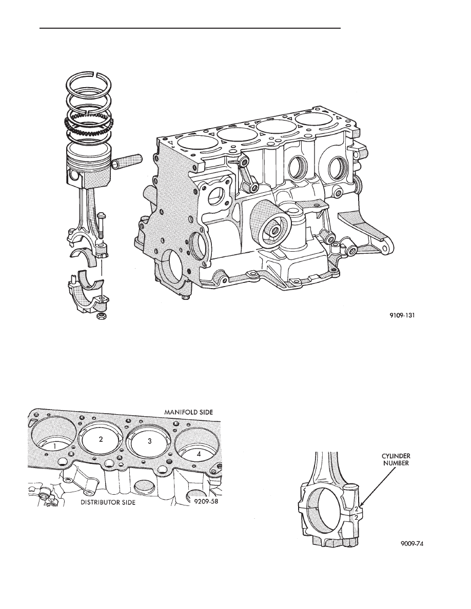
(1) Remove top ridge of cylinder bores with a reliable

ridge reamer before removing pistons from cylinder
block.Be sure to keep tops of pistons covered
during this operation
. Mark piston with matching
cylinder number (Fig. 2).

(2) Remove oil pan. Inspect connecting rods and

connecting rod caps for cylinder identification. Identify
them if necessary. (Fig. 3)

(3) Valve relief toward manifold side of engine.

(4) Squirt hole on connecting rod must face timing belt
end of engine.

(5) Pistons and connecting rods must be removed

from top of cylinder block. Rotate crankshaft so that
each connecting rod is centered in cylinder bore.

(6) Remove connecting rod cap. Install connecting

rod bolt protectors on connecting rod bolts (Fig. 4).
Push each piston and rod assembly out of cylinder bore.

Be careful not to nick crankshaft journals.
(7) After removal, install bearing cap on the mating

rod.

Fig. 1 Cylinder Block, Piston and Connecting Rod Assembly

Fig. 2 Piston Marking

Fig. 3 Identify Connecting Rod to Cylinder

.

2.5L ENGINE

9 - 27

CYLINDER BLOCK CLEANING AND INSPEC-
TION

(1) Clean cylinder block thoroughly and check all

core hole plugs for evidence of leaking.

(2) If new core plugs are installed, Refer to Engine

Core Oil and Cam Plugs.

(3) Examine block and cylinder bores for cracks or

fractures.

CYLINDER BORE INSPECTION

The cylinder walls should be checked for out- of-

round and taper with Tool C-119 (Fig. 5). If the cylinder
walls are badly scuffed or scored, the cylinder block
should be rebored and honed, and new pistons and
rings fitted. Whatever type of boring equipment is
used, boring and honing operation should be closely
coordinated with the fitting of pistons and rings in
order that specified clearances may be maintained.

Refer to Honing Cylinder Bores outlined in the
Standard Service Procedures for specification
and procedures.

Measure the cylinder bore at three levels in direc-

tions A and B (Fig. 5). Top measurement should be
10mm ( 3/8 inch) down and bottom measurement
should be 10mm ( 3/8 inch.) up from bottom of bore.
Refer to (Fig. 6) for specifications.

SIZING PISTONS

Piston and cylinder wall must be clean and dry.

Piston diameter should be measured 90 degrees to
piston pin at size location shown in (Fig. 7). Cylinder
bores should be measured halfway down the cylinder

Fig. 4 Connecting Rod Protectors

Fig. 5 Checking Cylinder Bore Size

Fig. 6 Piston Size Location and Clearance Chart

Fig. 7 Piston Installation and Sizing Information

9 - 28

2.5L ENGINE

.

bore and transverse to the engine crankshaft center
line shown in (Fig. 5). Refer to (Fig. 6) for specifica-
tions.

Pistons and cylinder bores should be measured

at normal room temperature, 70°F. (21°C).

PISTON RING—REMOVAL

(1) ID mark on face of upper and intermediate piston

rings must point toward piston crown.

(2) Using a suitable ring expander, remove upper

and intermediate piston rings (Fig. 8).

(3) Remove the upper oil ring side rail, lower oil ring

side rail and then oil ring expander from piston.

(4) Clean ring grooves of any carbon deposits.

FITTING RINGS

(1) Wipe cylinder bore clean. Insert ring and push

down with piston to ensure it is square in bore. The
ring gap measurement must be made with the ring
positioning at least 12mm (.50 inch) from bottom of
cylinder bore. Check gap with feeler gauge (Fig. 9).

Refer to specifications (Fig. 12).
(2) Check piston ring to groove clearance: (Fig. 10).

Refer to specification (Fig. 12).

PISTON RINGS—INSTALLATION

(1) The No. 1 and No. 2 piston rings have a different

cross section. Install rings with manufacturers I.D.
mark facing up, to the top of the piston (Fig. 11).

Fig. 8 Piston Rings—Removing and Installing

Fig. 9 Piston Ring Gap

Fig. 10 Measuring Piston Ring Groove Clearance

Fig. 11 Piston Ring End Gap Position

Fig. 12 Piston Ring Specifications

.

2.5L ENGINE

9 - 29

CAUTION: Install piston rings in the following order:

(a) Oil ring expander.
(b) Upper oil ring side rail.
(c) Lower oil ring side rail.
(d) No. 2 Intermediate piston ring.
(e) No. 1 Upper piston ring.

(2) Install the side rail by placing one end between

the piston ring groove and the expander. Hold end
firmly and press down the portion to be installed until
side rail is in position. Do not use a piston ring
expander 
(Fig. 13).

(3) Install upper side rail first and then the lower

side rail.

(4) Install No. 2 piston ring and then No. 1 piston

ring (Fig. 8).

(5) Position piston ring end gaps as shown in (Fig.

14).

(6) Position oil ring expander gap at least 45° from

the side rail gaps but not on the piston pin center or on
the thrust direction. Staggering ring gap is important
for oil control.

PISTON AND CONNECTING ROD ASSEMBLY
INSTALLATION

(1) Before installing pistons, and connecting rod

assemblies into the bore, besure that compression ring
gaps are staggered so that neither is in line with oil
ring rail gap.

(2) Before installing the ring compressor, make sure

the oil ring expander ends are butted and the rail gaps
located as shown in (Fig. 14).

(3) Immerse the piston head and rings in clean

engine oil, slide the ring compressor, over the piston
and tighten with the special wrench. Be sure position
of rings does not change during this operation 
.

(4) The valve cut should be toward the manifold side

of the engine (Fig. 16).

(5) Install connecting rod bolt protectors on rod bolts

(Fig. 4).

Fig. 13 Installing Side Rail

Fig. 14 Piston Ring End Gap Position

Fig. 15 Installing Piston

Fig. 16 Piston Markings

9 - 30

2.5L ENGINE

.


Content   ..  297  298  299  300   ..