Chrysler Town & Country/Voyager, Dodge Caravan, Plymouth Voyager. Manual - part 300


  Index      Chrysler     Chrysler Town & Country/Voyager, Dodge Caravan, Plymouth Voyager - service repair manual 1992 year


Search            


Content   ..  298  299  300  301   ..


Chrysler Town & Country/Voyager, Dodge Caravan, Plymouth Voyager. Manual - part 300


(6) Rotate crankshaft so that the connecting rod

journal is on the center of the cylinder bore. Insert rod
and piston into cylinder bore and guide rod over the
crankshaft journal.

(7) Tap the piston down in cylinder bore, using a

hammer handle. At the same time, guide connecting
rod into position on connecting rod journal.

(8) Install rod caps. Install nuts on cleaned and oiled

rod bolts and tighten nuts to 54 N

Im (40 ft. lb.) Plus 1/4

turn.

CONNECTING RODS

(1) Follow procedure specified in the Standard Ser-

vice Procedures Section for Measuring Main Bearing
Clearance and Connecting Rod Bearing Clearance
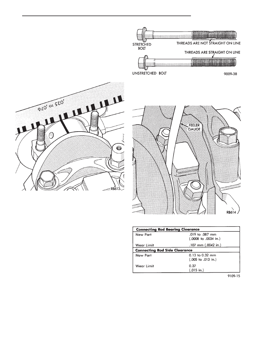
(Fig. 17). Refer to specifications (Fig. 20).

CAUTION: Do not rotate crankshaft or the Plastic-
Gage may be smeared.

The rod bearing bolts should be examined be-

fore reuse. If the threads are necked down the
bolts should be replaced (Fig. 18).

Necking can be checked by holding a scale or straight

edge against the threads. If all the threads do not
contact the scale the bolt should be replaced.

(2) Before installing the nuts the threads should be

oiled with engine oil.

(3) Install nuts on each bolt finger tight than alter-

nately torque each nut to assemble the cap properly.

(4) Tighten the nuts to 54 N

Im PLUS 1/4 turn (40 ft.

lbs. PLUS 1/4 turn). Do not use a torque wrench for
last step.

(5) Using a feeler gauge, check connecting rod side

clearance (Fig. 19). Refer to connecting rod specifica-
tions (Fig. 20).

ENGINE CORE PLUGS

REMOVAL

Using a blunt tool such as a drift or a screwdriver

and a hammer, strike the bottom edge of the cup

Fig. 17 Checking Connecting Rod Bearing Clear-

ance

Fig. 18 Checking Bolts for Stretching (Necked)

Fig. 19 Checking Connecting Rod Side Clearance

Fig 20 Connecting Rod Specifications

.

2.5L ENGINE

9 - 31

plug (Fig. 21). With the cup plug rotated, grasp firmly
with pliers or other suitable tool and remove plug (Fig.
21).

CAUTION: Do not drive cup plug into the casting as
restricted cooling can result and cause serious en-
gine problems.

INSTALLATION

Thoroughly clean inside of cup plug hole in cylinder

block or head. Be sure to remove old sealer. Lightly coat
inside of cup plug hole with sealer. Make certain the
new plug is cleaned of all oil or grease. Using proper
drive plug, drive plug into hole so that the sharp edge
of the plug is at least 0.5mm (.020 inch) inside the
lead-in chamfer (Fig. 21).

It is in not necessary to wait for curing of the sealant.

The cooling system can be refilled and the vehicle
placed in service immediately.

Fig. 21 Core Hole Plug Removal

9 - 32

2.5L ENGINE

.

CRANKSHAFT,INTERMEDIATE AND BALANCE
SHAFT ASSEMBLIES SERVICE

Fig. 1 Crankshaft Intermediate and Balance Shaft Assemblies and Oil Seals

.

2.5L ENGINE

9 - 33

CRANKSHAFT OIL SEALS SERVICE

(1) Pry out rear seal with screwdriver. Be careful not

to nick or damage crankshaft flange seal surface or
retainer bore (Fig. 2).

(2) Place Special Tool C-4681 on crankshaft (Fig. 3).
(3) Lightly coat seal O.D. with Loctite Stud N’ Bear-

ing Mount or equivalent.

(4) Place seal over Tool C-4681 and tap in place with

a plastic hammer.

REAR CRANKSHAFT SEAL RETAINER AND
OIL SEAL

When retainer removal is required, use Mopar Gas-

ket Maker applied as shown in (Fig 4.) to provide
retainer to block sealing during re-installation.

FRONT CRANKSHAFT SEAL RETAINER

See Timing System and Seals Section for timing belt

covers, belt, crankshaft sprocket and oil seals removal
and installation.

(1) Remove retainer screws (Fig. 5).

For reassembly Mopar Gasket Maker is applied to

the retainer as shown in (Fig. 6). This material cures in
the absence of air providing retainer to block sealing.

(2) Install retainer and tighten screws to 12 N

Im

(105 in. lbs.).

Fig. 2 Removing Rear Crankshaft Oil Seal

Fig. 3 Installing Rear Crankshaft Oil Seal

Fig. 4 Rear Crankshaft Seal Retainer Sealing

Fig. 5 Front Crankshaft Oil Seal Retainer

Fig. 6 Front Crankshaft Seal Retainer Sealing

9 - 34

2.5L ENGINE

.


Content   ..  298  299  300  301   ..