Chrysler Town & Country/Voyager, Dodge Caravan, Plymouth Voyager. Manual - part 297


  Index      Chrysler     Chrysler Town & Country/Voyager, Dodge Caravan, Plymouth Voyager - service repair manual 1992 year


Search            


Content   ..  295  296  297  298   ..


Chrysler Town & Country/Voyager, Dodge Caravan, Plymouth Voyager. Manual - part 297


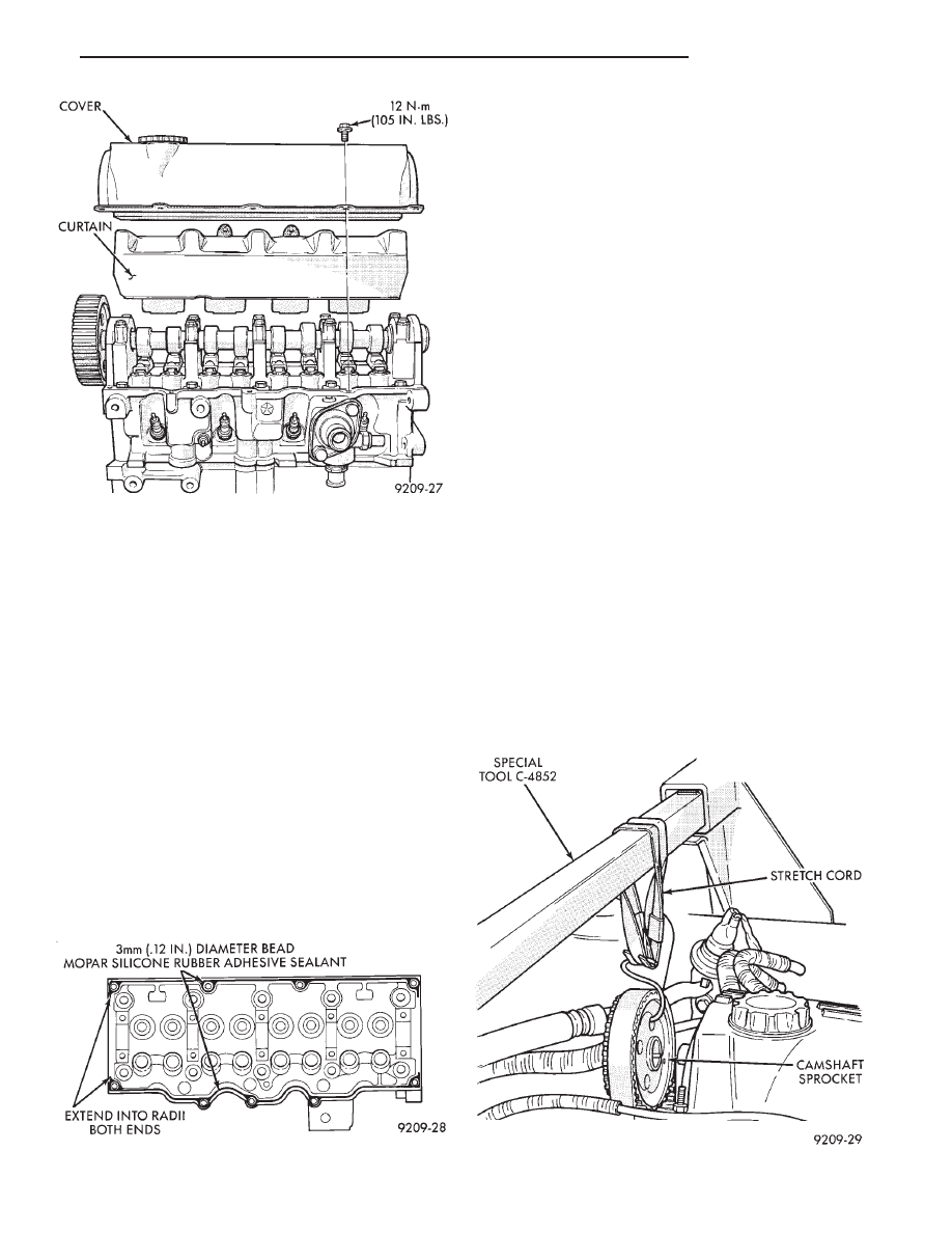
CYLINDER HEAD COVER AND CURTAIN

A curtain aiding air/oil separation is installed on the

cylinder head below the cylinder head cover (Figs. 1
and 2).

REMOVAL

(1) Remove the cylinder head cover bolts (Fig. 2).
(2) Remove cylinder head cover and curtain from

cylinder head. Do not misplace the rubber bumpers on
curtain.

CLEANING

Before installation, clean cylinder head and cover

mating surfaces. Make certain the rails are flat.

CURTAIN INSTALLATION

Install curtain manifold side first with cutouts over

cam towers and contacting cylinder head floor, then
press opposite distributor side into position below
cylinder head rail.

Curtain is retained in position with rubber bumpers

(Fig. 1).

COVER SEALING AND INSTALLATION

Before installation, clean cylinder head and cover

mating surfaces. Make certain rails are flat.

(1) Install new end seals on valve cover.
(2) Apply form-in-place Mopar Silicone Rubber Ad-

hesive Sealant or equivalent gasket material to cylin-
der head cover rail (Fig. 3). Refer to procedure detailed
in form-in-place gasket section of Standard Service
Procedures, in this Group.

Caution: Do not allow oil or solvents to contact the
timing belt as they can deteriorate the rubber and
cause tooth skipping.

(3) Install curtain, cover and end seal assembly to

head and tighten to 12 N

Im (105 in.lbs.) torque.

CYLINDER HEAD COMPONENTS—IN-VEHICLE
SERVICE

Removal and installation of cylinder head or cam-

shaft require separation of camshaft timing sprocket
from camshaft. To maintain camshaft, intermediate
shaft, and crankshaft timing during service proce-
dures, the timing belt is left indexed on the sprocket
while the assembly is suspended under light tension
(Fig. 4).

CAUTION: Failure to maintain adequate tension on
camshaft, intermediate, and crankshaft sprocket belt
can result in lost engine timing. If timing is lost, refer
to Timing System and Seals and (Fig. 4).

When removing the sprocket from the camshaft, you

must maintain adequate tension on the sprocket

Fig. 2 Cylinder Head Cover and Curtain

Fig. 3 Cylinder Head Valve Cover Rail Sealing

Fig. 4 Suspending Camshaft Sprocket

.

2.5L ENGINE

9 - 19

and belt assembly to prevent the belt from disengaging
with the intermediate or crankshaft timing sprockets.
Refer to Timing System and Seals for removal and
installation of camshaft sprocket procedure and to
Camshaft Service for removal and installation of cam-
shaft procedures.

CAMSHAFT SERVICE

Refer to TIMING SYSTEM AND SEALS for cam-

shaft timing belt and sprocket removal and installa-
tion, and CYLINDER HEAD In Vehicle Service.

REMOVAL

(1) Remove the cylinder head cover and curtain.
(2) Mark rocker arms for reinstallation in the same

position (Fig. 6).

(3) Loosen camshaft bearing cap screws several

revolutions (Fig. 7).

(4) Jar camshaft at rear of cam to loosen (break free)

the bearing caps. Use a soft faced mallet.

CAUTION: Care should be exercised not to cock the
camshaft during removal. Cocking of the camshaft
could cause damage to the cam or bearing thrust
surfaces.

(5) Remove screws and caps such that cam does not

cock.

INSPECTION

Check bearing cap and oil feed holes for blockage.
Inspect bearing cap and cylinder head journals for

wear and/or oversize, Refer to CYLINDER HEAD,
Inspect and Specifications.

Camshaft bearing journals and lobe wear. Lobe wear

should not exceed .25mm (.010 inch). To measure cam
lobe wear (Fig. 8), measure lobe diameter in two places
at the largest diameter (over the nose). Take first
reading

with

micrometer

in

unworn

area

Fig. 5 Engine Sprocket Timing

Fig. 6 Rocker Arm and Lash Adjuster

Fig. 7 Camshaft Cap Removal Sequence

Fig. 8 Camshaft

9 - 20

2.5L ENGINE

.

at the edge of the lobe. Take second reading in the worn
area where rocker arm contacts the lobe. Subtract
second reading from the first. The difference is the cam
lobe wear.

CAMSHAFT END PLAY

(1) Oil camshaft journals and install camshaft with-

out cam followers. Tighten screws to specified torque.

(2) Using a suitable tool, move camshaft as far

rearward as it will go.

(3) Zero dial indicator (Fig. 9).
(4) Move camshaft as far forward as it will go.
(5) End play travel: 0.13 - 0.33mm (0.005 - 0.013

inch).

(6) Remove bearing caps and camshaft.

INSTALLATION

(1) Install cam followers in correct order as removed.
(2) Align camshaft bearing caps in proper sequence

with Cap No. 1 at timing belt end and Cap No. 5 at
transmission end. Arrows on Caps No. 1, 2, 3, 4 must
point toward timing belt to prevent cap breakage (Fig.
10).

(3) Apply Mopar Gasket Maker to No.1 and No.5

bearing cap (Fig. 11).

(4) Caps must be installed before camshaft seals are

installed.

LASH ADJUSTER (TAPPET) NOISE

A tappet-like noise may be produced from several

items. Refer to Lash Adjuster and Tappet Noise -
Diagnosis in Standard Service Procedures, this Group.

VALVE COMPONENTS REPLACE—CYLINDER
HEAD NOT REMOVED

ROCKER ARM AND HYDRAULIC LASH AD-
JUSTER

REMOVAL

(1) Remove valve cover.
(2) For each rocker arm, rotate cam until base circle

is in contact with rocker arm. Depress valve spring
using Special Tool C-4682 (Fig. 12) and slide rocker
arm out. Keep rocker arms in order for reassembly.

(3) Remove hydraulic lash adjuster.

INSTALLATION

(1) Install hydraulic lash adjusters making sure that

adjusters are at least partially full of oil. This is
indicated by little or no plunger travel when the lash
adjuster is depressed.

(2) Rotate cam until base circle is in contact position

with rocker arm. Depress valve spring with Special
Tool C-4682 (Fig. 12) and slide rocker arm in place.
Keep rockers in order. It is possible for the valve spring
retainer locks to become dislocated when depressing
the valve spring. Check and make sure the locks
are in their proper location.

Fig. 9 Camshaft End Play

Fig. 10 Camshaft Bearing Caps Installation

Fig. 11 Cam Tower Cap Sealing

.

2.5L ENGINE

9 - 21

(3) Install valve cover as previously outlined in this

section.

VALVE SPRINGS AND VALVE STEM SEALS

REMOVAL

(1) Remove rocker arms as previously outlined in

this section.

(2) Rotate crankshaft until piston is at TDC on

compression.

(3) With air hose attached to adapter tool installed

in spark plug hole, apply 90-120 psi air pressure.

(4) Using Special Tool C-4682 (Fig. 12) compress

valve springs and remove valve locks.

(5) Remove valve spring.
(6) Remove valve stem seal by gently prying side-to-

side with a screwdriver blade. Once dislodged from
guide post, seal may be easily removed.

INSTALLATION

(1) Install valve seals (Fig. 13) as outlined in step (2)

of Valve Gear Reassembly - After Valve Service in
this section.

(2) Using Special Tool C-4682 compress valve

springs only enough to install locks. Correct alignment
of tool is necessary to avoid nicking valve stems (air
pressure required), piston at TDC.

(3) Install rocker arms as previously outlined in this

section.

CYLINDER HEAD

REMOVAL

(1) Perform fuel system pressure release procedure

before attempting any repairs. Refer to Fuel Sys-
tem Group 14.

(2) Disconnect negative battery cable. Drain cooling

system. Refer to Cooling System, Group 7.

(3) Remove air cleaner and disconnect all vacuum

lines, electrical wiring and fuel lines from throttle body.

(4) Remove throttle linkage.

(5) Loosen power steering pump and remove belt.
(6) Remove power brake vacuum hose from intake

manifold.

(7) Remove water hoses from water crossover.
(8) Raise vehicle and remove exhaust pipe from

manifold.

(9) Remove power steering pump assembly and set

aside.

(10) Disconnect coil wiring connector and coil wire

from coil.

(11) Disconnect dipstick tube from thermostat hous-

ing and ROTATE bracket from stud. DO NOT bend
the bracket.

(12) Refer to Solid Mount Compressor Bracket re-

moval in, this Group.

(13) Remove cylinder head cover and curtain from

head.

(14) Remove cylinder head bolts.

INSPECT HEAD AND CAMSHAFT BEARING
JOURNALS

(1) Cylinder head must be flat within 0.1mm (.004

inch)(Fig. 14).

(2) Inspect camshaft journals for scoring and journal

caps for oversize markings. When servicing cyl-

Fig. 12 Removing and Installing Valve Spring

Fig. 13 Valve Stem Seals

Fig. 14 Checking Cylinder Head Flatness

9 - 22

2.5L ENGINE

.


Content   ..  295  296  297  298   ..