Chrysler Town & Country/Voyager, Dodge Caravan, Plymouth Voyager. Manual - part 295


  Index      Chrysler     Chrysler Town & Country/Voyager, Dodge Caravan, Plymouth Voyager - service repair manual 1992 year


Search            


Content   ..  293  294  295  296   ..


Chrysler Town & Country/Voyager, Dodge Caravan, Plymouth Voyager. Manual - part 295


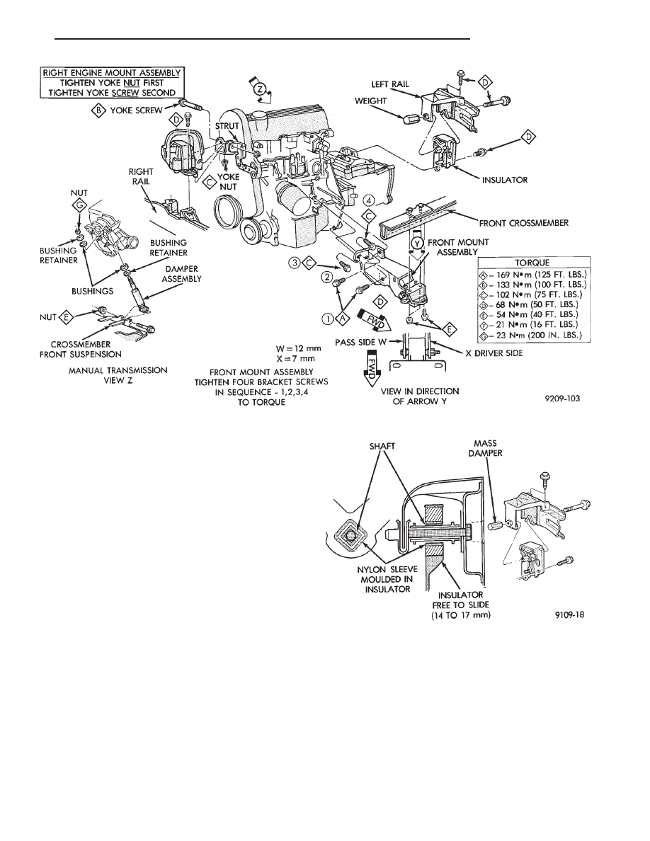
Left engine mount insulator is sleeved over

shaft and long support bolt to provide lateral
movement adjustment with engine weight re-
moved or not.

(3) Pry the engine right or left as required to achieve

the proper drive shaft assembly length. See Drive
Shaft in Suspension Group 2 for driveshaft identifica-
tion and related assembly length measuring.

(4) Tighten right engine mount insulator vertical

bolts to 37 N

Im (27 ft. lbs.). Then tighten front engine

mount screws and nuts to 54 N

Im (40 ft. lbs.) and

center left engine mount insulator.

(5) Recheck drive shaft length.

ENGINE ASSEMBLY

REMOVAL

(1) Disconnect battery.
(2) Scribe hood hinge outline on hood and remove

hood.

(3) Drain cooling system. Refer to Group 7 Cooling

System for procedure.

(4) Remove hoses from radiator and engine.
(5) Remove radiator and fan assembly (Fig. 5).
(6) Remove air cleaner and hoses.
(7) Remove air conditioning compressor mounting

bolts and set compressor aside (if so equipped).

(8) Remove power steering pump mounting bolts

and set pump aside.

(9) Remove oil filter.
(10) Disconnect fuel line, heater hose and accelera-

tor cable.

(11) Remove alternator mounting bolts and set alter-

nator aside.

(12) Disconnect

all

electrical

connections

from

throttle body, and engine.

(13) Manual Transmission

(a) Disconnect clutch cable.

Fig. 3 Engine Mounting

Fig. 4 Left Insulator Movement

.

2.5L ENGINE

9 - 11

(b) Remove transmission case lower cover.
(c) Disconnect exhaust pipe at manifold.
(d) Disconnect starter and lay aside.
(e) Install transmission holding fixture.

(14) Automatic Transmission

(a) Disconnect exhaust pipe at manifold.
(b) Disconnect starter and lay aside.
(c) Remove transmission case lower cover.
(d) Mark flex plate to torque converter.
(e) Remove screws holding torque converter to flex

plate.
(15) Attach C-clamp on front bottom of torque con-

verter housing to prevent torque converter from com-
ing out.

(16) Install transmission holding fixture.
(17) Remove right inner splash shield (Fig. 6).
(18) Remove ground strap.
(19) To lower engine, separate right engine bracket

from yoke bracket To raise engine, remove long bolt
through yoke and insulator. IF INSULATOR TO RAIL
SCREWS ARE TO BE REMOVED, MARK INSULA-
TOR POSITION ON SIDE RAIL TO INSURE EXACT
REINSTALLATION (Fig. 3).

(20) Remove transmission case to cylinder block

mounting screws.

(21) Remove front engine mount screw and nut.
(22) Remove left insulator through bolt (from inside

wheelhouse) or insulator bracket to transmission
screws.

(23) Remove engine from vehicle.

INSTALLATION

(1) Install hoist to the engine and lower engine into

the engine compartment.

SEE: ENGINE MOUNT RUBBER INSULATORS,

THIS GROUP.

(2) Align engine mounts and install but do not

tighten until all mounting bolts have been installed.
Tighten to 54 N

Im (40 ft. lbs.).

(3) Install transmission case to cylinder block

mounting screws. Tighten to 95 N

Im (70 ft. lbs.).

(4) Remove engine hoist and transmission holding

fixture.

(5) Secure ground strap.
(6) Install right inner splash shield.
(7) Connect starter. See Electrical Group 8 for instal-

lation.

(8) Connect exhaust system. See Exhaust Group 11

for installation.

(9) Manual Transmission Install transmission

case lower cover.

(10) Automatic Transmission Remove C clamp

from torque converter housing. Align flexplate to
torque converter and install mounting screws. Tighten
to 54 N

Im (40 ft. lbs.).

(11) Manual Transmission Connect clutch cable.

See Clutch Group 6.

(12) Install power steering pump (if equipped). Refer

to Cooling System Group 7 for belt tension adjustment.

(13) Install alternator. Refer to Cooling System

Group 7 for belt installation.

(14) Connect fuel line, heater hose, and accelerator

cable.

(15) Connect all electrical connections at alternator,

throttle body and engine.

(16) Install oil filter. Refill engine crankcase with

proper oil to correct level.

Fig. 5 Radiator and Fan Assembly

Fig. 6 Right Inner Splash Shield

9 - 12

2.5L ENGINE

.

(17) Reinstall

air

conditioning

compressor

(if

equipped). See Heater and Air Conditioning , Group 24
for installation.

(18) Reinstall air cleaner and hoses.
(19) Reinstall radiator and shroud assembly. Install

radiator hoses. Fill cooling system. Refer to Cooling
System Group 7 for filling procedure.

(20) Install hood.
(21) Connect battery.
(22) Start engine and run until operating tempera-

ture is reached.

(23) Adjust transmission linkage if necessary.

SOLID MOUNT COMPRESSOR BRACKET SERVICE

When service procedures require solid mount bracket

removal and installation for example: cylinder head
removal, etc., it is important that bracket fasteners
numbered 1 through 7 (Fig. 7) be removed and in-
stalled in sequence, as instructed in Removal and
Installation.

ACCESSORIES REMOVAL

(1) Remove (and install/adjust) belts, Refer to Acces-

sory Drive Belts in Cooling System, Group 7.

(2) Remove air conditioning compressor (in vehicle

with lines and set aside) (Fig. 7).

(3) Remove alternator pivot bolt and remove alter-

nator (in vehicle: turn wiring side up and disconnect,
then rotate alternator, pulley end towards engine and
remove).

(4) Remove air conditioner compressor belt idler.

SOLID MOUNT BRACKET—REMOVAL (FIG. 7)

(1) Remove right engine mount yoke screw. (Refer to

Engine Mounts (Fig. 3) securing isolator support
bracket to engine mount bracket.

(2) Remove five side mounting bolts #1, #4 , #5, #6,

and #7 (Fig. 7).

(3) Remove front mounting nut, #2, and remove (or

loosen) front bolt #3*.

*In vehicle: fully loosen bolt and remove with assem-

bly.

(4) Rotate solid mount bracket away from engine

and slide on stud (#2 nut mounting stud) until free.
Front mounting bolt and spacer will be removed with
bracket.

SOLID MOUNT BRACKET—INSTALLATION

Front mounting bolt and spacer need to be installed

simultaneously with bracket.

(1) Install bracket on front (#2 nut) mounting stud

and slide bracket over timing belt cover into position.

(2) Loosen assembly bracket to engine fasteners

(numbered #1 through #7 in Fig. 7).

CAUTION: Fasteners MUST BE TIGHTENED IN SE-
QUENCE and to specified torque as follows:

(3)

• First Bolt #1 to 30 NIm (30 in. lbs.)

• Second Nut #2 and Bolt #3 to 54 NIm (40 ft. lbs.).

• Third Bolts #1 (second tightening) #4 and #5 to 54
N

Im (40 ft. lbs.).

• Fourth Bolts #6 and #7 to 54 NIm (40 ft. lbs.).

(4) Install alternator and compressor. Tighten com-

pressor mounting bracket bolts to 54 N

Im (40 ft. lbs.).

Fig. 7 Solid Mount Compressor Bracket 2.5L Engines

.

2.5L ENGINE

9 - 13

TIMING SYSTEM AND SEALS SERVICE

Refer to (Fig. 1) for parts identification and torque

specifications

TIMING BELT SERVICE

(1) Remove Solid Mount Compressor Bracket. Refer

to procedure outlined in this section.

(2) Raise vehicle on a hoist and remove right inner

splash shield (Fig. 2).

(3) Remove screws retaining water pump pulley and

bolts retaining crankshaft pulley (Fig. 3) and lay pulley
aside.

(4) Remove nuts holding cover to cylinder head.

Fig. 1 Timing System and Seals

Fig. 2 Right Inner Splash Shield

Fig. 3 Crankshaft and Water Pump Pulley

9 - 14

2.5L ENGINE

.


Content   ..  293  294  295  296   ..