Chrysler Town & Country/Voyager, Dodge Caravan, Plymouth Voyager. Manual - part 293


  Index      Chrysler     Chrysler Town & Country/Voyager, Dodge Caravan, Plymouth Voyager - service repair manual 1992 year


Search            


Content   ..  291  292  293  294   ..


Chrysler Town & Country/Voyager, Dodge Caravan, Plymouth Voyager. Manual - part 293


scuffing, scoring or scratches. Usually a few strokes
will clean up a bore and maintain the required limits.

(2) Deglazing of the cylinder walls may be done

using a cylinder surfacing hone, Tool C-3501, equipped
with 280 grit stones (C-3501-3810) if the cylinder bore
is straight and round. 20-60 strokes depending on the
bore condition will be sufficient to provide a satisfac-
tory surface. Inspect cylinder walls after each 20
strokes. Using a light honing oil available from major
oil distributors. Do not use engine or transmission
oil, mineral spirits or kerosene.

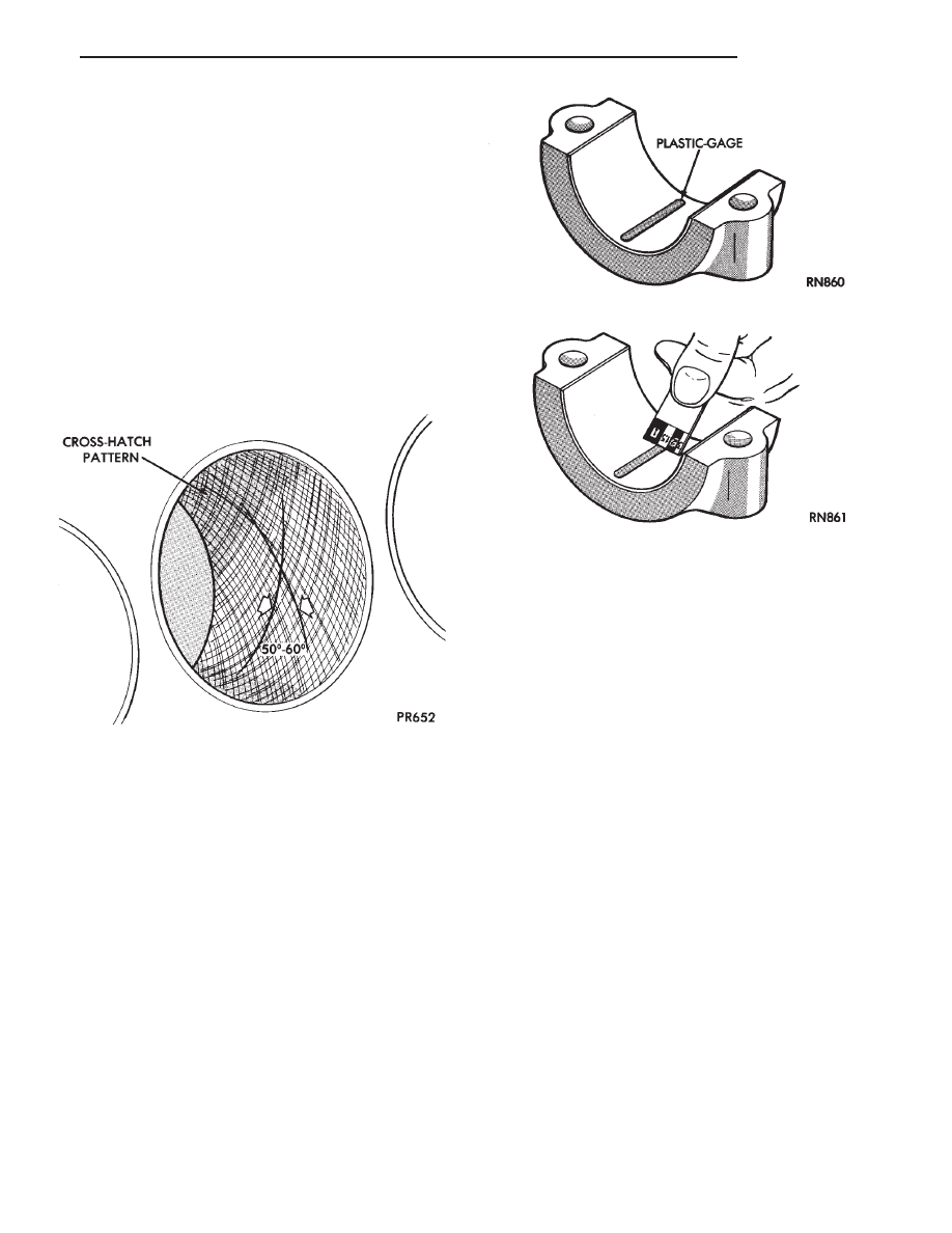
(3) Honing should be done by moving the hone up

and down fast enough to get a cross-hatch pattern.
When hone marks intersect at 50-60 degrees, the
cross hatch angle is most satisfactory for proper seat-
ing of rings (Fig. 1).

(4) A controlled hone motor speed between 200-300

RPM is necessary to obtain the proper cross-hatch
angle. The number of up and down strokes per minute
can be regulated to get the desired 50-60 degree angle.
Faster up and down strokes increase the cross-hatch
angle.

(5) After honing, it is necessary that the block be

cleaned again to remove all traces of abrasive.

CAUTION: Be sure all abrasive are removed from
engine parts after honing. It is recommended that a
solution of soap and hot water be used with a brush
and the parts then thoroughly dried. The bore can be
considered clean when it can be wiped clean with a
white cloth and cloth remains clean. Oil the bores
after cleaning to prevent rusting.

MEASURING MAIN BEARING CLEARANCE AND
CONNECTING ROD BEARING CLEARANCE

PLASTIGAGE METHOD

Engine crankshaft bearing clearances can be deter-

mined by use of Plastigage or equivalent. The following
is the recommended procedure for the use of Plasti-
gage:

(1) Remove oil film from surface to be checked.

Plastigage is soluble in oil.

(2) The total clearance of the main bearings can

only be determined by removing the weight of the
crankshaft. This can be accomplished by either of two
methods:

PREFERRED METHOD — Shimming the bear-

ings adjacent to the bearing to be checked in order to
remove the clearance between upper bearing shell and
the crankshaft. This can be accomplished by placing a
minimum of 0.254mm (.010 inch) shim (e. g. cardboard,
matchbook cover, etc.) between the bearing shell and
the bearing cap on the adjacent bearings and snugging
bolts to 14-20 N

Im (10-15 ft.lb.)

• When checking #1 main brg shim #2 main brg

• When checking #2 main brg shim #1 & 3 main brg

• When checking #3 main brg shim #2 & 4 main brg

• When checking #4 main brg shim #3 & 5 main brg

• When checking #5 main brg shim #4 main brg

Fig. 1 Cylinder Bore Cross-Hatch Pattern

Fig. 2 Plastigage Placed in Lower Shell

Fig. 3 Clearance Measurement

.

ENGINE

9 - 3

REMOVE ALL SHIMS BEFORE REASSEM-

BLING ENGINE

ALTERNATIVE METHOD — With the weight of

the crankshaft being supported by a jack under the
counterweight adjacent to the bearing being checked.

(3) Place a piece of Plastigage across the entire

width of the bearing shell in the cap approximately
6.35mm (1/4 inch) off center and away from the oil
holes (Fig. 2). (In addition, suspect areas can be
checked by placing the Plastigage in the suspect area).
Torque the bearing cap bolts of the bearing being
checked to the proper specifications.

(4) Remove the bearing cap and compare the width

of the flattened Plastigage (Fig. 3) with the metric scale
provided on the package. Locate the band closest to the
same width. This band shows the amount of clearance
in thousandths of a millimeter. Differences in readings
between the ends indicate the amount of taper present.
Record all readings taken. Refer to Engine Specifica-
tions. Plastigage generally is accompanied by two
scales. One scale is in inches, the other is a
metric scale.

(5) Plastigage is available in a variety of clearance

ranges. The 0.025-0.076mm (.001-.003 inch) is usually
the most appropriate for checking engine bearing
proper specifications.

CONNECTING ROD BEARING CLEARANCE

Engine crankshaft bearing clearances can be deter-

mined by use of Plastigage or equivalent. The following
is the recommended procedure for the use of Plasti-
gage:

(1) Rotate the crankshaft until the connecting rod to

be checked is at the bottom of its stroke.

(2) Remove oil film from surface to be checked.

Plastigage is soluble in oil.

(3) Place a piece of Plastigage across the entire

width of the bearing shell in the bearing cap approxi-
mately 6.35 mm (1/4 inch.) off center and away from
the oil hole (Fig. 2). In addition, suspect areas can be
checked by placing plastigage in the suspect area.

(4) Before assembling the rod cap with Plastigage in

place, the crankshaft must be rotated until the con-
necting being checked starts moving toward the top of
the engine. Only then should the cap be assembled and
torqued to specifications. Do not rotate the crank-
shaft while assembling the cap or the Plastigage
may be smeared, giving inaccurate results.

(5) Remove the bearing cap and compare the width

of the flattened Plastigage (Fig. 3) with the metric scale
provided on the package. Locate the band closest to the
same width. This band shows the amount of clearance
in thousandths of a millimeter. Differences in readings
between the ends indicate the amount of taper present.
Record all readings taken. Refer to Engine Specifica-
tions. Plastigage generally is accompanied by two
scales. One scale is in inches, the other is a
metric scale.

(6) Plastigage is available in a variety of clearance

ranges. The 0.025-0.076mm (.001-.003 inch) is usually
the most appropriate for checking engine bearing
proper specifications.

LASH ADJUSTER (TAPPET) NOISE DIAGNOSIS

A tappet-like noise may be produced from several

items. Check the following items.

(1) Engine oil level too high or too low. This may

cause aerated oil to enter the adjusters and cause them
to be spongy.

(2) Insufficient running time after rebuilding cylin-

der head. Low speed running up to 1 hour may be
required.

During this time, turn engine off and let set for a few

minutes before restarting. Repeat this several times
after engine has reached normal operating tempera-
ture.

(3) Low oil pressure.
(4) The oil restrictor pressed into the vertical oil

passage to the cylinder head Balance Shaft Engines
Only is plugged with debris.

(5) Air ingested into oil due to broken or cracked oil

pump pick up.

(6) Worn valve guides.
(7) Rocker arm ears contacting valve spring retainer

(2.5L engines).

(8) Rocker arm loose, adjuster stuck or at maximum

extension and still leaves lash in the system.

(9) Faulty lash adjuster.

(a) Check for sponginess while still installed in

cylinder head. Depress part of rocker arm just over
adjuster. Normal adjusters should feel very firm.
Spongy adjusters can be depressed to the bottomed
position easily.

(b) Remove suspected lash adjusters, pry off re-

tainer cap and disassemble Do not reuse retainer
caps
. Do not interchange parts and make sure that
care and cleanliness is exercised in the handling of
parts.

(c) Clean out dirt and varnish with solvent.
(d) Reassemble with engine oil.
(e) Check for sponginess.
(f) If still spongy, replace with new adjuster.

REPAIR OF DAMAGED OR WORN THREADS

Damaged or worn threads (including aluminum head

spark plug threads) can be repaired. Essentially, this
repair consists of drilling out worn or damaged
threads, tapping the hole with a special Heli-Coil (or
equivalent) Tap, and installing an insert into the
tapped hole. This brings the hole back to its original
thread size.

CAUTION: Be sure that the tapped holes maintain the
original centerline.

9 - 4

ENGINE

.

Heli-Coil tools and inserts are readily available from

automotive parts jobbers.

HYDROSTATIC LOCKED ENGINE

When an engine is suspected to be hydrostaticly

locked, regardless of what caused the problem, these
steps should be used.

CAUTION: Do Not Use Starter Motor To Rotate En-
gine, severe damage may occur.

(1) Inspect air cleaner, induction system and intake

manifold to insure system is dry and clear of foreign
material.

(2) Remove negative battery cable.
(3) Place a shop towel around the spark plugs when

removing them from the engine. This will catch any
fluid that may possibly be in the cylinder under pres-
sure.

(4) With all spark plugs removed, rotate engine

crankshaft using a breaker bar and socket.

(5) Identify the fluid in the cylinder(s) (i.e., coolant,

fuel, oil or other).

(6) Make sure all fluid has been removed from the

cylinders. Inspect engine for damage (i.e., Connecting
Rods, Pistons, Valves etc.)

(7) Repair engine or components as necessary to

prevent this problem from occurring again.

CAUTION: Squirt approximately 1 teaspoon of oil into
cylinders, rotate engine to lubricate the cylinder walls
to prevent damage on restart.

(8) Install new spark plugs.
(9) Drain engine oil and remove oil filter.
(10) Fill engine with specified amount of approved

oil and install new oil filter.

(11) Connect negative battery cable.
(12) Start engine and check for any leaks.

.

ENGINE

9 - 5

ENGINE DIAGNOSIS—PERFORMANCE

9 - 6

ENGINE

.


Content   ..  291  292  293  294   ..