Chrysler Town & Country/Voyager, Dodge Caravan, Plymouth Voyager. Manual - part 231


  Index      Chrysler     Chrysler Town & Country/Voyager, Dodge Caravan, Plymouth Voyager - service repair manual 1992 year


Search            


Content   ..  229  230  231  232   ..


Chrysler Town & Country/Voyager, Dodge Caravan, Plymouth Voyager. Manual - part 231


POWER WINDOWS

CONTENTS

page

page

GENERAL INFORMATION

. . . . . . . . . . . . . . . . . . 1

MOTOR REPLACEMENT

. . . . . . . . . . . . . . . . . . . 2

POWER VENT WINDOWS . . . . . . . . . . . . . . . . . . 3
POWER WINDOW CABLE HOUSING/MOTOR

REPLACEMENT

. . . . . . . . . . . . . . . . . . . . . . . . 2

SWITCH CONTINUITY TEST

. . . . . . . . . . . . . . . . 1

SWITCH VOLTAGE TEST . . . . . . . . . . . . . . . . . . . 1
VENT CABLE AND CRANK MECHANISM

. . . . . . 4

VENT WINDOW MOTOR REPLACEMENT

. . . . . . 5

VENT WINDOW MOTOR TEST

. . . . . . . . . . . . . . 3

VENT WINDOW SWITCH TEST . . . . . . . . . . . . . . 3
WINDOW MOTOR TEST

. . . . . . . . . . . . . . . . . . . 2

GENERAL INFORMATION

Window lift motors are of the permanent magnet

type. A positive and negative battery connection to
either of the two motor terminals will cause the motor
to rotate in one direction. Reversing current through
these same two connections will cause the motor to
rotate in the opposite direction.

Each individual motor is grounded through the mas-

ter switch by a black wire attached to the left cowl
panel.

It is necessary that the window be free to slide up

and down in the glass channels or tubes and tracks. If
the window is not free to move up and down, the
window lift motor will not be able to move the glass.

To determine if the glass is free is to disconnect the

electric window regulator lift plate from the glass (Fig.
1). Then slide the window up and down by hand.
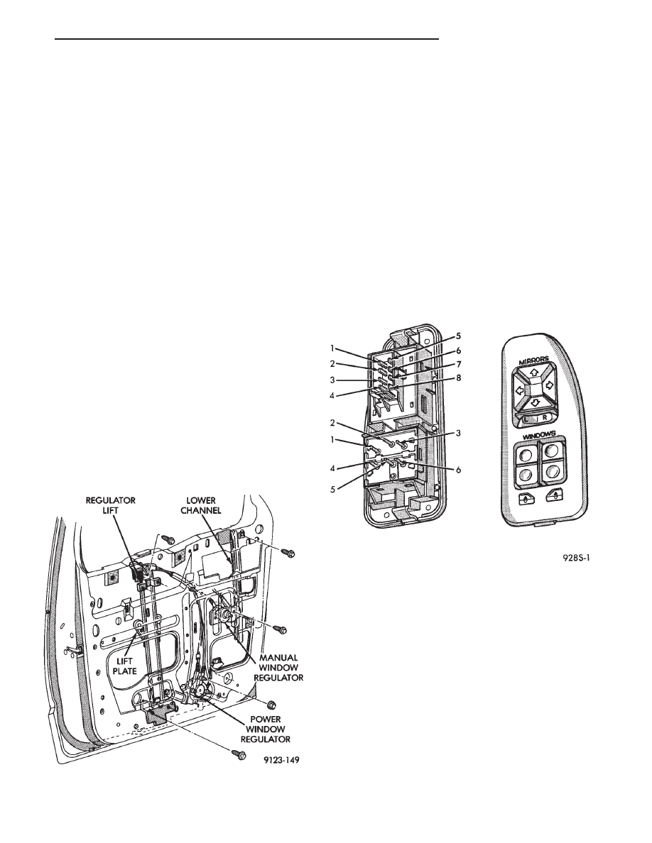
SWITCH VOLTAGE TEST

The following wiring test sequence determines

whether or not voltage is continuous through the body
harness to switch (Fig. 2).

(1) After removing switch from trim panel for testing

purposes, carefully separate multiple terminal block
on wiring harness from switch body.

(2) Connect one lead of test light to black wire

terminal and touch other test light lead to tan wire
terminal.

(3) If the test light comes on, the wiring circuit

between the battery and switch is functional.

(3) If light does not come on, check 30 amp circuit

breaker or for a broken wire.

SWITCH CONTINUITY TEST

To check the switch, remove the switch from its

mounting position. Using an ohmmeter, and referring
to the Switch Continuity (Figs. 3 and 4), determine if
continuity is correct. If there is no continuity at any one
of

the

switch

positions,

replace

the

switch.

Fig. 1 Power Window Regulator

Fig. 2 Mirror/Window Switch

.

POWER WINDOWS

8S - 1

WINDOW MOTOR TEST

(1) Connect positive (+) lead from a test battery to

either of the two motor terminals.

(2) Connect negative (-) lead from test battery to

remaining motor terminal.

(3) The motor should now rotate in one direction to

either move window up or down.

(a) If window happens to be already in full UP

position and motor is connected so to rotate in UP
direction no movement will be observed.

(b) Also, the motor connected to DOWN direction

rotation, no movement will be observed if window is
already in full down position.

(4) Reverse battery leads (steps 1 and 2) and window

should now move. If window does not move, remove
motor. See below for motor removal from vehicle.

(5) If window moved completely up or down, motor

should be reversed one more time (step 4) to complete
a full window travel inspection.

POWER WINDOW CABLE HOUSING/MOTOR RE-
PLACEMENT

(1) Remove front door trim panel. Refer to group 23,

Body.

(2) Disconnect window lift plate from glass (Fig. 5).

(3) Disconnect window track from door.
(4) Disconnect window lift motor and drive cables.
(5) Disconnect electrical connections.
(6) Carefully remove window track, cables and lift

motor assembly from door.

(7) For installation reverse above procedures.

MOTOR REPLACEMENT

REMOVAL

(1) Refer to Front Door Window Regulator for re-

moval.

(2) The door glass must be in the full up position.
(3) Tape glass to door frame to hold glass in the up

position.

(4) If the window is not in the full up position,

remove only the motor from the door.

(5) Remove nuts from motor and cable housing (Fig.

6).

(6) Make sure motor is facing you before separating

motor from housing.

(7) Using a flat tool slowly separate motor from

housing, making sure the cable drum under the motor
stays in cable housing. When motor is fully separated
the assist spring will be completely unwound (Fig. 7).

(8) Remove assist spring by releasing the tabs on the

opposite sides of the spring, do not remove spring from
its case (Fig. 8).

INSTALLATION

(1) Install motor into housing with one stud and in

center of housing to secure motor to housing.

Fig. 3 Master Switch Continuity

Fig. 4 Front Door Window or Rear Vent Window

Switch Continuity

Fig. 5 Cable and Housing/Motor

8S - 2

POWER WINDOWS

.

(2) Before installing new spring, power the motor

into the full-up position.

(3) Replace assist spring on cable housing. Wind

spring clockwise 3 1/2 turns on the left door. The right
door, wind spring counter clockwise 3 1/2 turns (Fig. 9).

(4) Install the other two studs and nuts and tighten

to 4 to 5 M

Im (35 to 45 in. lbs.).

(5) Inspect that cables are not twisted prior to in-

stalling motor and housing into door.

POWER VENT WINDOWS

AS-body vehicles have, as an option, power rear vent

windows. The windows are operated by switches
mounted in the overhead console. A separate switch is
used for each window.

The vent window motors are of the permanent mag-

net type. A positive and negative battery connection to
either of the two motor terminals will cause the motor
to rotate in one direction. Reversing current through
these same two connections will cause the motor to
rotate in the opposite direction.

VENT WINDOW SWITCH TEST

For power vent window switch testing, see power

windows Switch Test.

VENT WINDOW MOTOR TEST

(1) Connect positive (+)lead from a test battery to

either of the two motor terminals.

(2) Connect negative (-) lead from test battery to

remaining motor terminal.

(3) The motor should now rotate in one direction to

either move the window OPEN or CLOSED.

(a) If window happens to be already in the full

CLOSED position and motor is connected to rotate
toward the CLOSED position no movement will be
observed.

(b) Also, the motor connected to rotate OPEN, no

movement will be observed if the window is already
in full OPEN position.
(4) Reverse battery leads (opposite steps 1 and 2)

and window should now move, or move in the opposite
direction. If window does not move, remove motor and
cable assembly.

Fig. 6 Separating Motor from Housing

Fig. 7 Cable/Drum and Motor

Fig. 8 Assist Spring Cover

Fig. 9 Wind Assist Spring Cover

.

POWER WINDOWS

8S - 3

(5) If

window

moved

completely

OPEN

and

CLOSED, motor should be reversed one more time
(reverse leads from step 4) to complete a full window
movement inspection.

VENT CABLE AND CRANK MECHANISM

REMOVAL

(1) Remove windshield side garnish molding.
(2) Remove rear seat(s).
(3) Remove front door and liftgate scuff plates.
(4) If servicing right side cable, remove side door

scuff plate and upper track cover.

(5) Remove B-pillar garnish molding and seat belt.
(6) Remove upper and lower trim panels for the left

side or one piece trim panel for the right side.

(7) Remove two bolts attaching crank mechanism to

quarter panel (Fig. 10).

(8) Remove three screws attaching cable to motor.
(9) Disengage pivot from quarter glass.
(10) Remove cable retaining clip and remove cable

assembly.

INSTALLATION

(1) Position cable to motor making sure cable pulley

engages with motor and install three screws (Fig. 11).

(2) Engage pivot to quarter glass.
(3) Install crank mechanism bolts and pull mecha-

nism rearward while tightening (Proper alignment is
required for smooth non-binding operation).

(4) Install cable retaining clip.

(5) Install upper and lower trim panels for the left

side or one piece trim panel right side.

(6) Install B pillar garnish molding and seat belt.
(7) Install side door scuff plate and upper track

cover.

(8) Install front door scuff plate, liftgate scuff plate,

rear seat(s) and windshield side garnish molding.

Fig. 10 Motor and Cable Assemblies

Fig. 11 Cable Attaching Screws

8S - 4

POWER WINDOWS

.


Content   ..  229  230  231  232   ..