Chrysler Town & Country/Voyager, Dodge Caravan, Plymouth Voyager. Manual - part 230
POWER SEATS
CONTENTS
page
page
ADJUSTER
. . . . . . . . . . . . . . . . . . . . . . . . . . . . . 3
CIRCUIT BREAKER TEST
. . . . . . . . . . . . . . . . . . 1
GENERAL INFORMATION
. . . . . . . . . . . . . . . . . . 1
HARNESS VOLTAGE TEST
. . . . . . . . . . . . . . . . . 1
HORIZONTAL AND VERTICAL
TRANSMISSIONS . . . . . . . . . . . . . . . . . . . . . . . 3
MOTOR
. . . . . . . . . . . . . . . . . . . . . . . . . . . . . . . . 3
MOTOR CABLE AND HOUSING
. . . . . . . . . . . . . 2
MOTOR TESTS
. . . . . . . . . . . . . . . . . . . . . . . . . . 1
SEAT ASSEMBLY
. . . . . . . . . . . . . . . . . . . . . . . . 2
SWITCH TEST
. . . . . . . . . . . . . . . . . . . . . . . . . . . 2
TEST PROCEDURES
. . . . . . . . . . . . . . . . . . . . . . 1
GENERAL INFORMATION
Driver’s power seat can be adjusted in six different
directions up, down, forward, back, tilt forward, or tilt
rearward.
A three armature permanent magnet reversible mo-
tor is coupled through cables to worm gear box assem-
blies located in the seat tracks, providing the various
seat movements.
The electrical circuit is protected by a 30 amp circuit
breaker located on the fuse block.
TEST PROCEDURES
Before any testing is attempted the battery should be
carefully charged and all connections and terminals
cleaned and tightened to insure proper continuity and
grounds.
With dome lamp on, apply switch in direction of
failure. If dome lamp dims the seat motion is trying to
work indicating mechanical jamming. If dome lamp
does not dim, then proceed with the following electrical
tests.
CIRCUIT BREAKER TEST
Find correct circuit breaker on fuse block. Pull out
slightly but be sure that circuit breaker terminals still
contact terminals in fuse block. Connect ground wire of
voltmeter to a good ground. With probe of voltmeter
positive wire, check both terminals of circuit breaker
for battery voltage. If only one terminal checks at
battery voltage, circuit breaker is defective and must
be replaced. If neither terminal shows battery voltage,
check for open or shorted circuit to circuit breaker.
HARNESS VOLTAGE TEST
The following test will determine whether or not
voltage is continuous through the body harness to the
switch.
(1) Remove power seat switch from mounting posi-
tion and disconnect switch from wiring harness.
(2) Connect one lead of test light to ground terminal,
black wire (BK) of center section, and touch other test
light lead to red wire (RD) terminal.
(3) If test light comes on, harness to switch is good.
If test light does not come on, perform circuit breaker
test.
MOTOR TESTS
(1) Remove switch from mounting position and dis-
connect from harness (Fig. 1).
(2) To check the front motor, connect a covered
jumper wire between cavity number 2 and cavity
number 9. Connect a second jumper wire between
cavity number 6 and cavity number 5. If the motor does
not operate, reverse the jumpers (2 to 5 and 6 to 9). If
motor still does not operate check wiring between
switch connector and motor assembly. If wiring checks
good replace motor assembly.
(3) To check the center motor, connect a covered
jumper wire between cavity number 2 and cavity
number 8. Connect a second jumper wire between
cavity 6 and cavity number 7. If the motor does not
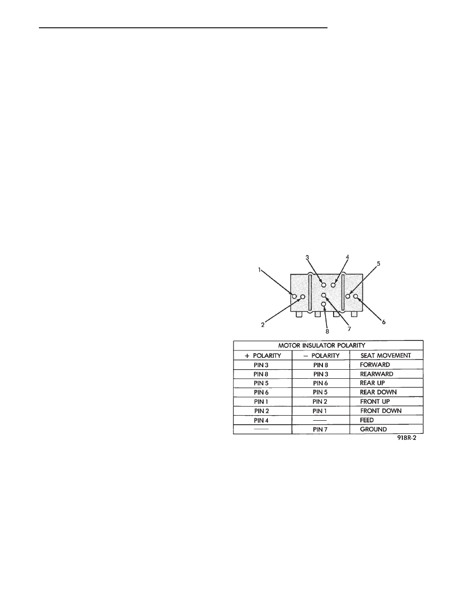
Fig. 1 Power Seat Switch Connector
.
POWER SEATS
8R - 1