Chrysler Town & Country/Voyager, Dodge Caravan, Plymouth Voyager. Manual - part 228


  Index      Chrysler     Chrysler Town & Country/Voyager, Dodge Caravan, Plymouth Voyager - service repair manual 1992 year


Search            


Content   ..  226  227  228  229   ..


Chrysler Town & Country/Voyager, Dodge Caravan, Plymouth Voyager. Manual - part 228


REAR WINDOW DEFOGGER

CONTENTS

page

page

ACCESSORY SWITCH CARRIER TEST

. . . . . . . . 2

ACCESSORY SWITCH CARRIER . . . . . . . . . . . . . 1
GENERAL INFORMATION

. . . . . . . . . . . . . . . . . . 1

REAR WINDOW GRID LINES TEST

. . . . . . . . . . 2

REPAIR GRID LINES, TERMINALS

AND PIGTAILS

. . . . . . . . . . . . . . . . . . . . . . . . . 3

SYSTEM TEST . . . . . . . . . . . . . . . . . . . . . . . . . . . 1

GENERAL INFORMATION

The electrically heated rear window defogger (Fig. 1)

is available on single rear door wagons and vans.

The system consists of two vertical bus bars and a

series of electrically connected grid lines on the inside
surface of the rear window.

When the switch is turned to the ON position,

current is directed to the rear window grid lines. The
heated grid lines in turn heat the rear window to clear
the outside surface of the glass.

CAUTION: Since grid lines can be damaged or
scraped off with sharp instruments, care should be
taken in cleaning the glass or removing foreign ma-
terials, decals or stickers. Normal glass cleaning
solvents or hot water used with rags or toweling is
recommended.

ACCESSORY SWITCH CARRIER

The accessory switch carrier is integrated into a the

accessory switch carrier assembly. An indicator lamp
illuminates when the switch is activated. Actuating the
switch energizes the electronic timing circuit which
allows current to flow through the grid system for
approximately 10 minutes, or until either the control
switch or ignition is turned off. If the liftgate release
switch is actuated, the power to control switch is
momentarily opened until liftgate switch is released,
but the indicator lamp will stay illuminated.

SYSTEM TEST

Electrically heated rear window defogger operation

can be checked on the vehicle in the following manner:

(1) Turn the ignition ON.
(2) Turn rear window defogger control switch ON.
(3) Using a ammeter on the battery, turn the Defog-

ger control switch to the ON position, a distinct in-
crease in amperage draw should be noted.

(4) The rear window defogger operation can be

checked by feeling the glass. A distinct difference in
temperature between the grid lines and adjacent clear
glass can be detected in 3 to 4 minutes of operation.

(5) Using a DC voltmeter (Fig. 2) contact terminal B

with the negative lead, and terminal A with the posi-
tive lead. The voltmeter should read 10-14 volts.

(6) Only steps (3) and (4) or (5) above will confirm

system operation. Indicator light illumination means
that there is power available at the output of the relay
only, and does not necessarily verify system operation.

(7) If turning the switch ON produced no distinct

current draw on the ammeter the problem should be
isolated in the following manner:

(a) Confirm that ignition switch is ON.
(b) Ensure that the heated rear window feed pig-

tail is connected to the wiring harness and that the
ground pigtail is in fact grounded.

(c) Ensure that the fusible link or circuit breaker

is operational.

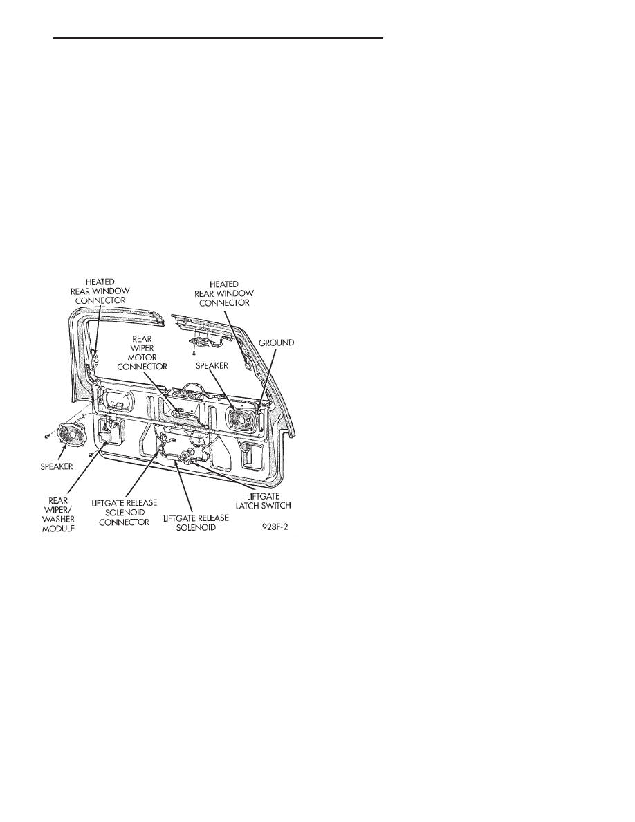
Fig. 1 Rear Window Defogger Wiring

.

REAR WINDOW DEFOGGER

8N - 1

(8) When the above steps have been completed and

the system is still inoperative, one or more of the
following is defective:

(a) Accessory Switch Carrier
(b) Check for loose connector or a wire pushed out

of connector.

(c) Rear window grid lines (all grid lines would

have to be broken, or one of the feed pigtails not
connected to the bus bar, for no ammeter deflection).
(9) If turning the switch ON produces severe voltme-

ter deflection, the circuit should be closely checked for
a shorting condition.

(10) If the system operation has been verified but

indicator LED does not light, replace switch.

(11) For detailed wiring information, refer to Group

8W, Wiring Diagrams.

REAR WINDOW GRID LINES TEST

The horizontal grid lines and vertical bus bar lines

printed and baked on inside surface of rear window
glass makes up an electrical parallel circuit. The elec-
trically conductive lines are composed of a silver ce-
ramic material which when baked on glass becomes
bonded to the glass and is highly resistant to abrasion.
It is possible, however, that a break may exist or occur
in an individual grid line resulting in no current flow
through the line. To detect breaks in grid lines, the
following procedure is required:

(1) Turn ignition and rear window defogger control

switch ON. The indicator light should come on.

(2) Using a DC voltmeter with 0-15 volt range,

contact vertical bus bar connecting grid lines on pas-
senger side of vehicle at terminal A (Fig. 2) with
negative lead of voltmeter. With positive lead of volt-
meter, contact vertical bus bar on driver side of vehicle
at terminal B (Fig. 2). The voltmeter should read 10-14
volts.

(3) With negative lead of voltmeter, contact a good

body ground point. The voltage reading should not
change. A different reading indicates a poor ground
connection.

(4) Connect negative lead of voltmeter to terminal A

on passenger side bus bar and touch each grid line at
Mid-Point with positive lead. A reading of approxi-
mately 6 volts indicates a line is good. A reading of 0
volts indicates a break in line between Mid-Point C and
terminal B. A reading of 10-14 volts indicates a break
between Mid-Point C and ground terminal A. Move
toward break and voltage will change as soon as break
is crossed.

ACCESSORY SWITCH CARRIER TEST

Accessory switch carrier may be tested in-vehicle or

bench tested. In vehicle testing is accomplished in the
following manner:

(1) Remove the accessory switch carrier assembly

from the instrument panel or console, see Group 8E,
Instrument Panel and leave the switch connector
plugged in (Fig. 3).

(2) Turn ignition ON.
(3) Using a DC voltmeter, with 0-15 range, check

voltage at terminals B, D and A. (Figs. 3 and 4).Termi-
nals B and D should confirm a voltage of 10 to 14 volts
to ground. Terminal A should confirm voltage to
ground. When terminals B and D show no voltage,
trace circuit upstream of accessory switch carrier for
problem, example; wiring cut, fusible link or circuit
breaker inoperative, bulkhead connector not operative,
etc.. If terminal A indicates voltage, place switch in Off
position. If voltage at terminal A is still indicated or
indicator lamp remains on, the accessory switch carrier
should be replaced.

(4) If the relay checks out to this point, momen-

tarily operate switch to ON position. The indicator
lamp should come on and remain on for approxi-
mately 10 minutes. Terminal A should confirm volt-

Fig. 2 Grid Line Test

Fig. 3 Accessory Switch Carrier

8N - 2

REAR WINDOW DEFOGGER

.

age. If the indicator lamp fails to light or voltage at
terminal A is not confirmed replace accessory switch
carrier.

Bench checking of the relay may be accomplished in

the following manner. By following the in-vehicle pro-
cedure except Step 2: With a DC power supply, apply 12
volts to terminal B and 4 and ground terminal E.

REPAIR GRID LINES, TERMINALS AND PIGTAILS

The repair of grid lines and replacement of the

terminal is possible using the Mopar Repair Package or
equivalent.

(1) Clean area surrounding grid line or terminal by

gently rubbing area with steel wool.

(2) Wipe area with clean cloth soaked in alcohol or

similar solvent. It is necessary that all contaminants
be removed from repair area.

(3) Remove package separator clamp and mix plastic

conductive epoxy thoroughly.

(4) For grid line, mark off area to be repaired with

masking tape (Fig.5).

(5) Apply conductive epoxy through slit in masking

tape. Overlap both ends of the break.

(6) For a terminal replacement, apply a thin layer of

epoxy to area where terminal was fastened.

(7) Apply a thin layer of epoxy on terminal and place

terminal on desired location. To prevent terminal from
falling off use a wooden wedge to secure it.

(8) Carefully remove masking tape from grid line.

CAUTION: Do not allow the glass surface to exceed
204°C (400°F), glass may fracture.

(9) Allow epoxy to cure 24 hours at room tempera-

ture or use heat gun with a 260°-371°C (500°-700°F)
range for 15 minutes. Hold gun approximately 254mm
(10 inches) from repaired area.

(10) After epoxy is properly cured remove wedge

from terminal and check the operation of the rear
window defogger.

WARNING: REPAIR KIT MAY CAUSE SKIN OR EYE
IRRITATION. CONTAINS EPOXY RESIN AND AMINE
TYPE

HARDENER,

HARMFUL

IF

SWALLOWED.

AVOID CONTACT WITH SKIN AND EYES. FOR SKIN,
WASH AFFECTED AREAS WITH SOAP AND WATER.
DO NOT TAKE INTERNALLY. IF TAKEN INTERNALLY,
INDUCE VOMITING; CALL A PHYSICIAN IMMEDI-
ATELY. IF IN CONTACT WITH EYES, FLUSH WITH
PLENTY OF WATER. USE WITH ADEQUATE VENTILA-
TION. DO NOT USE NEAR FIRE OR FLAME. CON-
TENTS CONTAINS 3

FLAMMABLE SOLVENTS.
WARNING: KEEP OUT OF REACH OF CHILDREN.

Fig. 4 Rear Window Defogger Circuit—Typical

Fig. 5 Grid Line Repair—Typical

.

REAR WINDOW DEFOGGER

8N - 3


Content   ..  226  227  228  229   ..