Chrysler Town & Country/Voyager, Dodge Caravan, Plymouth Voyager. Manual - part 222
MODULE TEST
(1) Remove liftgate trim panel. Refer to Group 23,
Body.
(2) Using a volt/ohmmeter test each pin and repair
as necessary.
(a) Pin 1, test for module output battery voltage to
wiper motor, with the ignition switch in the ON
position and the rear wiper switch ON (Fig. 17).
(b) Pin 2, test for battery voltage from ignition
switch, with the ignition in the ON position.
(c) Pin 3, test for continuity to ground.
(d) Pin 4, ignition switch ON and the rear window
washer switch ON, test for battery voltage.
(e) Pin 5, ignition switch ON and wiper switch ON,
test for continuity to ground. The intermittent mode
will have an eight second delay between wipes.
(f) Pin 6, ignition switch ON and washer switch
pushed in, test continuity to ground.
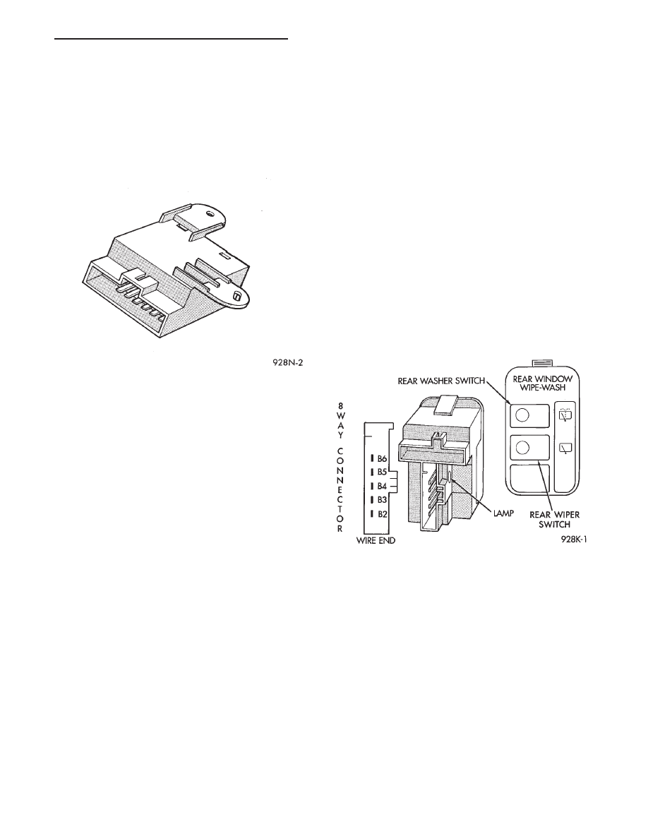
REAR WIPER/WASHER CONTROL POD SWITCH
(1) The Rear Wiper switch portion of this assembly
is a push ON, push OFF latching action and provides:
• Rear wiper operates with a fixed intermittent cycle.
• A ground signal to the rear wash/wipe module to
turn the rear wiper system ON (fixed intermittent)
when rear wiper button is latched down.
• There shall be continuity between terminals B5 and
B2 when the rear wiper button is depressed and
latched down.
• When the rear wiper button is latched, the ON
indicator lamp will light only when headlamps are on.
• If not replace rear wiper/washer control POD switch.
(2) The Rear Washer switch portion of this assembly
is a push ON, momentary action and provides:
• A ground signal to the rear wash/wipe module to
turn the rear washer system ON when the rear wash
button is depressed.
• There shall continuity between terminals B4 and B3
only when the front washer button is depressed.
• If not replace rear wiper/washer control POD switch.
(3) Serviceable: lamp control the illumination of the
switch assembly. The lamp is feed by terminals B6
(power) and B5 (ground).
REAR WIPER/WASHER CONTROL POD SWITCH
REPLACEMENT
(1) Remove warning indicator grille by prying up
with a flat blade tool.
(2) Remove three mounting screws from the warning
indicator module assembly.
(3) Remove eight screws mounting the cluster bezel
to the instrument panel.
(4) Tilt column down if possible for ease.
(5) Gently pull cluster bezel out, to gain access to the
switch assembly’s snap fingers and push switch out
through mounting hole for POD switch assembly (Fig.
18).
(6) Remove wiring connectors for POD switch as-
sembly.
(7) Remove lamp.
(8) For installation reverse above procedures. Verify
the functions of the front and rear wipe/wash system.
LIFTGATE WIPER MOTOR TEST
The following test is used to locate and then repair
liftgate wiper motor defects. Refer to Group 8W, Wiring
Diagrams for liftgate wiper motor wiring schematic.
(1) Disconnect feed wire connector from wiper motor
(Fig. 19).
(2) With ignition switch in ON position, check for
battery voltage at blue wire.
Fig. 17 Intermittent Wipe Module
Fig. 18 Rear Wiper/Washer Control POD Switch
.
WINDSHIELD WIPER AND WASHER SYSTEMS
8K - 11