Chrysler Town & Country/Voyager, Dodge Caravan, Plymouth Voyager. Manual - part 221


  Index      Chrysler     Chrysler Town & Country/Voyager, Dodge Caravan, Plymouth Voyager - service repair manual 1992 year


Search            


Content   ..  219  220  221  222   ..


Chrysler Town & Country/Voyager, Dodge Caravan, Plymouth Voyager. Manual - part 221


(b) If there is no continuity, the problem is an open

circuit in the wiper control switch or wiring harness.

WIPER MOTOR REPLACEMENT

(1) Remove windshield wiper arms (Fig. 5).
(2) Open hood assembly.
(3) Remove cowl top plenum grille.

(4) Remove hoses from hose connectors.
(5) Remove cowl plenum chamber plastic screen.
(6) Remove wiper pivot retaining screws.
(7) Push pivots down into plenum chamber.
(8) Remove nut from wiper motor output shaft and

remove linkage assembly.

(9) Disconnect wiper motor wiring harness.
(10) Remove mounting screw and nuts from wiper

motor.

(11) Remove wiper motor.
(12) Perform disassembly and service on pieces as

necessary.

(13) For installation reverse above procedures. Ex-

cept the following torque specifications:

(a) Tighten motor mounting screw and nuts 7 to 8

N

Im (60 to 70 in. lbs.) torque.

(b) Tighten pivot screws 7 to 8 N

Im (60 to 70 in.

lbs.) torque.

(c) Position wiper motor drive crank on motor

shaft and tighten retaining nut 10 to 11 N

Im (90 to

100 in.lbs.) torque.

(d) Refer to Wiper Arm Adjustment for proper

alignment.

INTERMITTENT WINDSHIELD WIPER MOTOR AND SWITCH

INDEX

page

page

Intermittent Function Tests

. . . . . . . . . . . . . . . . . . . 8

Intermittent Windshield Wiper Switch

. . . . . . . . . . . 8

Intermittent Wiper Motor Test

. . . . . . . . . . . . . . . . . 7

INTERMITTENT WIPER MOTOR TEST

Intermittent Wiper Motor Service Procedures for

diagnosis of problems which, do not involve the delay
function, refer to the Motor Tests. The two-speed func-
tions of all wiper motors are identical.

If a problem occurs, only in the DELAY mode, the

following tests are to be performed.

CONDITION: EXCESSIVE DELAY OF MORE
THAN 30 SECONDS OR INADEQUATE VARIA-
TION IN DELAY

REPAIR

Variations in delay should be as follows:
(1) Minimum delay control to extreme counterclock-

wise position before first detent of one half to two
seconds.

(2) Maximum delay control to extreme clockwise

position before off detent of ten to thirty seconds.

(3) If there is excessive delay or no variations in

delay go to intermittent wipe switch test.

CONDITION: IN DELAY MODE WIPERS RUN
CONTINUALLY WHEN WASH IS OPERATED
BUT DO NOT PROVIDE AN EXTRA WIPE
WHEN THE WASH CONTROL IS RELEASED

REPAIR

Replace the body controller.

CONDITION: WIPERS START ERRATICALLY DURING DELAY
MODE

REPAIR

(1) Verify that the ground connection at the instru-

ment panel is making good connection, free from paint
and is tight.

(2) Verify that the motor ground strap is making

good contact and that the motor mounting bolts are
tight.

(3) Verify that the wiring ground connections for the

intermittent wipe control unit and the wiper switch are
tight.

(4) If condition is not corrected, replace body control-

ler.

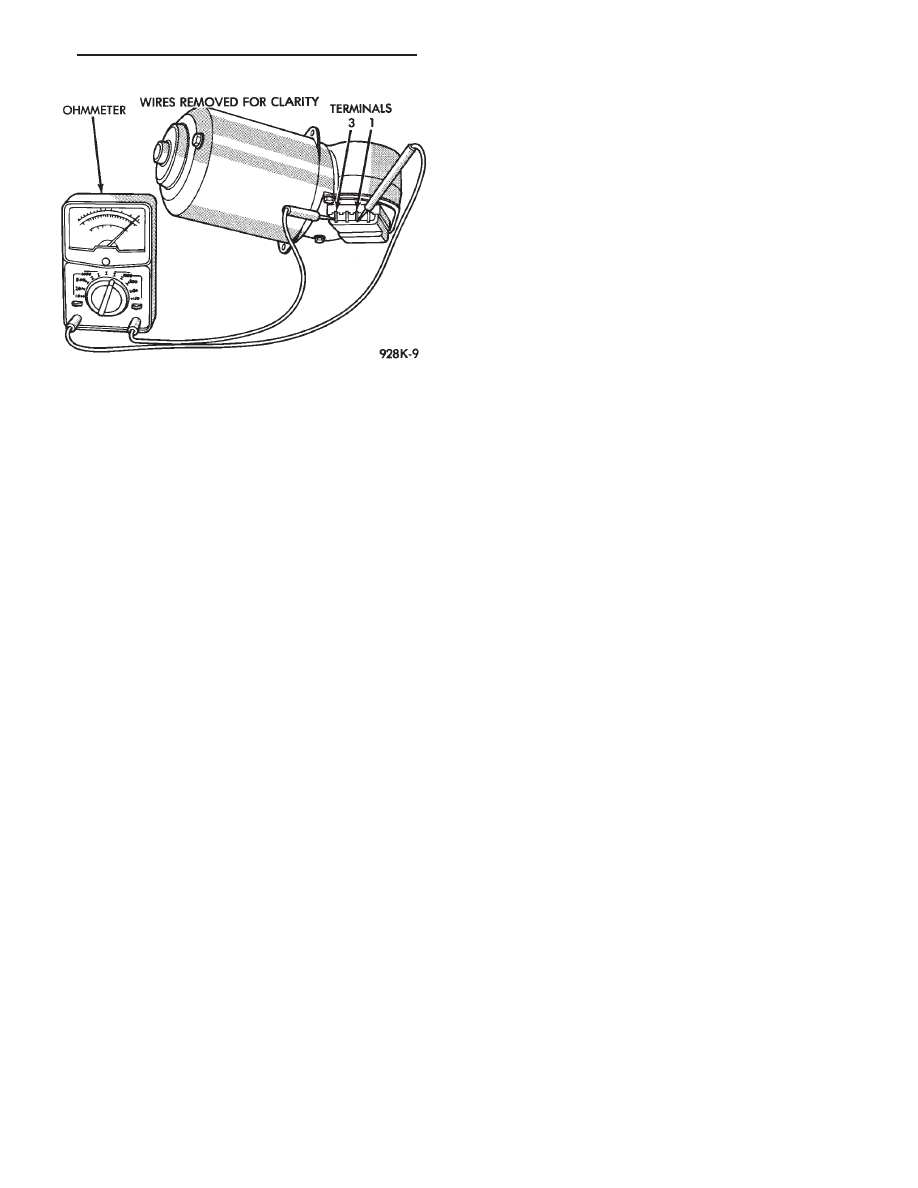
Fig. 12 Ohmmeter Between Terminals 3 and 1

.

WINDSHIELD WIPER AND WASHER SYSTEMS

8K - 7

INTERMITTENT WINDSHIELD WIPER SWITCH

WARNING: ON VEHICLES EQUIPPED WITH AIR-

BAG, SEE GROUP 8M, RESTRAINT SYSTEMS FOR
STEERING WHEEL OR COLUMN REMOVAL PROCE-
DURES.

The intermittent wipe function is controlled by the

body controller, located at the lower right side of
steering column. If the body controller is determined to
be the problem, refer to Group 8E, Instrument Panels
and Gauges, for replacement procedures.

To test the intermittent wipe functions a DRB II will

be needed, and the Body Diagnostic Procedures
Manual.

The DRB II is used to monitor the intermittent wipe

input, washer input and the dwell switch input.

To test the switch, first disconnect the switch wires

from the body wiring in the steering column. Using an
ohmmeter, test for continuity between the terminals of
the switch, as indicated in the following continuity
chart. The identity of each terminal is shown in Fig. 13.

For test purposes, the first position is the OFF

position, next is the slide for the DELAY wipe. LOW is
the next detent position and HIGH is the full counter-
clockwise detent position.

In any wiper mode, if the knob is pushed all the way

in, the washer circuit will be completed.

The wiper switch is part of the multi-function switch

assembly. If the wiper switch fails, the multi-function
switch must be replaced. Refer to Group 8J, Turn
Signals and Hazard Warning Flasher for multi-
function switch service procedure.

INTERMITTENT FUNCTION TESTS

CONDITION: EXCESSIVE DELAY, MORE THAN
30 SECONDS OR INADEQUATE VARIATION IN
DELAY

REPAIR

Variations in delay should be as follows:
(1) Minimum delay control to extreme counterclock-

wise position before first detent of one half to two
seconds.

(2) Maximum delay control to extreme clockwise

position before off detent of ten to thirty seconds.

(3) If there is excessive delay or no variations in

delay go to intermittent wipe switch test.

(4) If not within specifications, replace body control-

ler.

CONDITION: IN DELAY MODE WIPERS RUN
CONTINUALLY WHEN WASH IS OPERATED
BUT DO NOT PROVIDE AN EXTRA WIPE
WHEN THE WASH CONTROL IS RELEASED

REPAIR

Replace the body controller.

CONDITION: WIPERS START ERRATICALLY
DURING DELAY MODE

REPAIR

(1) Verify that the ground connection at the instru-

ment panel is making good connection, free from paint
and is tight.

(2) Verify that the motor ground strap is making

good contact and that the motor mounting bolts are
tight.

(3) Verify that the wiring ground connections for the

intermittent wipe control unit and the wiper switch are
tight.

(4) If condition is not correct, replace body controller.

Fig. 13 Multi-Function Switch Connector and Inter-

mittent Wipe Continuity

8K - 8

WINDSHIELD WIPER AND WASHER SYSTEMS

.

WINDSHIELD WASHERS

INDEX

page

page

General Information

. . . . . . . . . . . . . . . . . . . . . . . . 9

Washer Nozzle

. . . . . . . . . . . . . . . . . . . . . . . . . . 10

Washer Reservoir Pump Replacement

. . . . . . . . . . 9

Washer Reservoir Removal

. . . . . . . . . . . . . . . . . . 9

GENERAL INFORMATION

All models are equipped with electric operated wind-

shield washer pumps.

The wash function can be accessed in the OFF

position of the wiper control switch. Holding the wash
button depressed when the switch is in the OFF
position will operate the wipers and washer motor
pump continuously until the washer button is released.
Releasing the button will stop the washer pump. The
wipers will complete the current wipe cycle followed by
an average of two more wipe cycles (

61) before the

wipers park and the module turns off.

Whenever a windshield washer malfunction occurs,

verify that the windshield washer wire harness is
properly connected before starting normal diagnosis
and repair procedures. Refer to Windshield Washer
Diagnosis Chart (Fig. 14).

WASHER RESERVOIR REMOVAL

(1) Unlock and open the hood.

(2) Remove screws attaching the reservoir in ple-

num.

(3) Disconnect the wiring harness from the reservoir

pump and sensor, if equipped.

(4) Disconnect the washer hose and block the liquid

outlet to prevent the liquid from running out while
removing the reservoir from engine compartment.

(5) For

installation

reverse

above

procedures.

Tighten attaching screws to 3 N

Im (26 in. lbs.) torque.

WASHER RESERVOIR PUMP REPLACEMENT

(1) Remove washer reservoir and pump assembly,

refer to Reservoir Removal.

(2) Notice position of pump, then using a 19mm (3/4

in.) socket through the liquid filler opening, loosen the
pump filter and nut.

(3) Disconnect the outside portion of the pump.

Fig. 14 Windshield Washer Diagnosis

.

WINDSHIELD WIPER AND WASHER SYSTEMS

8K - 9

(4) Remove inner and outer portions of the pump.
(5) For installation reverse above procedures.

(a) Install rubber grommet into place in bottom of

reservoir.

(b) Refer to Washer Reservoir Removal for instal-

lation of reservoir.

WASHER NOZZLE

These models are equipped with two washer nozzles

attached to the wiper arms. Each arm emits five

streams across the wiper pattern. No adjustment is
required. If nozzle performance is unsatisfactory they
should be replaced. The right and left nozzles are
identical.

To replace unsnap nozzle from wiper arm and discon-

nect hose. When installing make sure that both the
nozzle and the hose guard are securely snapped into
position.

REAR WINDOW WIPER/WASHER SYSTEM

INDEX

page

page

Liftgate Motor Replacement

. . . . . . . . . . . . . . . . . 12

Liftgate Washer Reservoir Pump Replacement

. . . 13

Liftgate Washer Reservoir Removal

. . . . . . . . . . . 12

Liftgate Wiper Motor Test

. . . . . . . . . . . . . . . . . . . 11

Module Test

. . . . . . . . . . . . . . . . . . . . . . . . . . . . . 11

Rear Arm Adjustment

. . . . . . . . . . . . . . . . . . . . . . 10

Rear Window Intermittent Wipe Module Location

. . 10

Rear Wiper/Washer Control Pod Switch

. . . . . . . . 11

Rear Wiper/Washer Control Pod Switch

Replacement

. . . . . . . . . . . . . . . . . . . . . . . . . . . 11

Washer Nozzle

. . . . . . . . . . . . . . . . . . . . . . . . . . 13

For wiper blade service, refer to windshield Wiper

Blades.

REAR ARM ADJUSTMENT

(1) With the motor in park position, mount the arm

on the motor shaft. Choose a serration engagement
that properly locates tip of the blade about 90 mm (3
1/2 inch) parallel, with lower edge of liftgate glass (Fig.
15).

(2) Operate the wiper on dry glass with the engine

off. The tip of the wiper blade should be within 60 mm
(2 3/8 inch) to 120 mm (4 3/4 inch) above lower edge of
liftgate glass.

REAR WINDOW INTERMITTENT WIPE MODULE
LOCATION

The intermittent wipe module is located inside the

lift gate on the right van side (Fig. 16).

Fig. 15 Installing Liftgate Wiper Arm

Fig. 16 Intermittent Wipe Module Location

8K - 10

WINDSHIELD WIPER AND WASHER SYSTEMS

.


Content   ..  219  220  221  222   ..