Chrysler Town & Country/Voyager, Dodge Caravan, Plymouth Voyager. Manual - part 220


  Index      Chrysler     Chrysler Town & Country/Voyager, Dodge Caravan, Plymouth Voyager - service repair manual 1992 year


Search            


Content   ..  218  219  220  221   ..


Chrysler Town & Country/Voyager, Dodge Caravan, Plymouth Voyager. Manual - part 220


(3) Set arm on pivot and push down.
(4) Lift arm and push latch in to release arm to

windshield.

(5) For proper alignment of wiper arm, refer to

Wiper Arm Adjustment.

WIPER ARM ADJUSTMENT

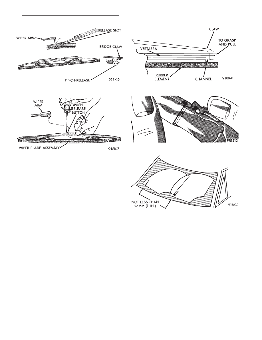
(1) Cycle the wiper motor into the PARK position.
(2) Check the tips of the blades in blackout area.

From the bottom edge of the windshield to the blade
should be no closer than 25 mm (1 inch) (Fig. 6).

(3) Operate the wipers if the requirements are not

met, check linkage and pivot assembly for worn parts.

Fig. 4 Wiper Blade and Element

Fig. 5 Removing Wiper Arm

Fig. 2 Wiper Blade and Element

Fig. 3 Wiper Blade and Element

Fig. 6 Windshield Wiper Arm Adjustment

.

WINDSHIELD WIPER AND WASHER SYSTEMS

8K - 3

WINDSHIELD WIPER MOTOR AND LINKAGE

INDEX

page

page

Motor Tests

. . . . . . . . . . . . . . . . . . . . . . . . . . . . . . 4

Wiper Motor Replacement

. . . . . . . . . . . . . . . . . . . 7

WARNING: ON VEHICLES EQUIPPED WITH AIRBAG,
SEE GROUP 8M, RESTRAINT SYSTEMS FOR STEER-
ING WHEEL OR COLUMN REMOVAL PROCEDURES.

The following is a list of general wiper motor system

problems. The tests are to be performed to locate the
faulty part and the corrective action to be taken. These
tests will cover both two speed and intermittent wipe
functions, refer to Windshield Wiper Motor Diagnosis
(Fig. 7).

MOTOR TESTS

CONDITION: MOTOR WILL NOT RUN IN ANY
SWITCH POSITION

REPAIR

(1) Check for a blown fuse in the fuse block.

(a) If fuse is good, go to step 2.
(b) If fuse is defective, replace and check motor

operation in all switch positions.

(c) If motor is still inoperative and the fuse does

not blow, go to step 2.

(d) If replacement fuse blows, go to step 5.

(2) Place switch in LOW speed position.
(3) Listen to motor. If you cannot hear it running, go

to Step No. 4. If you hear it running, check motor
output shaft. If output shaft is not turning, replace
motor assembly. If it is turning, drive link to output
shaft or linkage is not properly connected. Replace
worn parts and/or properly connect drive link to the
motor output shaft.

(4) Connect a voltmeter between motor terminal 3

and ground strap (Fig. 8). If there is no voltage or very
little voltage (less than one volt) present, move nega-
tive test lead from the ground strap to negative battery
terminal.

(a) If an increase in voltage is noticed, the problem

is a bad ground circuit. Make sure the motor mount-
ing is free of paint and that nuts or bolts are tight.

(b) If there is still no indication of voltage, the

problem is an open circuit in the wiring harness or
wiper switch.

(c) If no noticeable increase greater than 3 volts is

observed, the problem is a faulty motor assembly.
(5) Disconnect motor wiring connector and replace

fuse.

(a) If fuse does not blow, motor is defective.
(b) If fuse blows, switch or wiring is at fault.

CONDITION: MOTOR RUNS SLOWLY AT ALL
SPEEDS

REPAIR

(1) Disconnect wiring harness connector at motor.

Remove wiper arms and blades. Connect an ammeter
between battery (B+) and terminal 3 on motor (Fig. 9).

(a) If motor runs and average ammeter reading is

more than 6 amps, go to step 2.

(b) If motor runs and average ammeter reading is

less than 6 amps, go to step 3.
(2) Check to see if wiper linkage or pivots are bind-

ing or caught. Disconnect drive link from motor.

(a) If motor now runs and draws less than 3 amps,

repair linkage system.

(b) If motor continues to draw more than 3 amps,

replace motor assembly.
(3) Check motor wiring harness for shorting be-

tween high and low speed wires as follows:

(a) Connect a voltmeter or test lamp to motor

ground strap.

(b) Set wiper switch to LOW position.
(c) Connect other lead of voltmeter to terminal 4 of

the wiring harness.

(d) If voltage is present, there is a short in the

wiring or wiper switch.

(e) If no voltage is present set wiper switch to

HIGH position.

(f) Move voltmeter lead from terminal 4 to termi-

nal 3 of the wiring harness.

(g) If voltage is present, there is a short in the

wiring or wiper switch.

CONDITION: MOTOR WILL RUN AT HIGH
SPEED, BUT NOT AT LOW SPEED OR

MOTOR WILL RUN AT LOW SPEED, BUT NOT AT

HIGH SPEED.

REPAIR

(1) If motor will not run on high speed, put switch in

HIGH position and connect a test lamp between motor
Terminal 4 and ground (Fig. 10).

8K - 4

WINDSHIELD WIPER AND WASHER SYSTEMS

.

Fig. 7 Windshield Wiper Motor Diagnosis

.

WINDSHIELD WIPER AND WASHER SYSTEMS

8K - 5

(2) If motor will not run on low speed, put switch in

LOW position and connect a test lamp between motor
Terminal 3 and ground.

(3) If test lamp does not light at motor terminal,

there is an open in wiring or switch. If test lamp lights
at motor terminal, replace motor assembly.

CONDITION: MOTOR KEEP RUNNING WITH
SWITCH IN OFF POSITION

REPAIR

Remove wiring harness. Connect jumper from Termi-

nal 1 to Terminal 3 of wiper motor (Fig. 11). Connect
second jumper from Terminal 2 to battery (B+). If
motor runs to PARK position and stops, wiper switch is
faulty. If motor keeps running and does not park,
replace motor assembly.

CONDITION: MOTOR WILL STOP, WHEN
SWITCH IS SET IN OFF POSITION. WIPERS DO
NOT CONTINUE RUNNING TO PARK POSI-
TION.

REPAIR

(1) Remove motor wiring connector and clean termi-

nals. Reconnect connector and test motor. If problem
persists, go to Step 2.

(2) Set wiper switch to OFF position. Disconnect

motor wiring connector. Connect a voltmeter or test
lamp to the motor ground strap. Connect the other lead
to terminal 2 of wiring connector.

(a) If voltage is not present, check for an open

circuit in the wiring harness or wiper control switch.

(b) If voltage is present, go to step 3.

(3) Connect an ohmmeter or continuity tester be-

tween terminals 3 and 1 (Fig. 12).

(a) If there is continuity between these terminals,

the problem is a defective motor.

Fig. 8 Voltmeter Between Terminal 3 and Ground

Fig. 9 Ammeter Between Terminal 3 and Battery

Fig. 10 Test Lamp Between Terminal 4 and Ground

Fig. 11 One Jumper Wire Between Terminal 1 and 3.

One Jumper Wire Between Terminal 2 and Battery

Positive

8K - 6

WINDSHIELD WIPER AND WASHER SYSTEMS

.


Content   ..  218  219  220  221   ..