Chrysler Town & Country/Voyager, Dodge Caravan, Plymouth Voyager. Manual - part 218


  Index      Chrysler     Chrysler Town & Country/Voyager, Dodge Caravan, Plymouth Voyager - service repair manual 1992 year


Search            


Content   ..  216  217  218  219   ..


Chrysler Town & Country/Voyager, Dodge Caravan, Plymouth Voyager. Manual - part 218


(c) If continuity, refer to Stop Lamp Switch Test.
(d) If stop lamp switch test OK, Test continuity

between pin 6 of stop lamp switch and ground.
(14) Using an ohmmeter, touch one lead to a good

body ground and touch the other lead to pin 30. The
meter should show no continuity when transmission is
in DRIVE and continuity when in PARK or NEUTRAL.
If not test Neutral Start and Back-Up switch using
DRB II.

SPEED CONTROL SWITCH TEST

WARNING: IF REMOVAL OF AIR BAG MODULE IS

NECESSARY, REFER TO GROUP 8M, RESTRAINT
SYSTEMS.

(1) Remove the switch and disconnect 4-way connec-

tor.

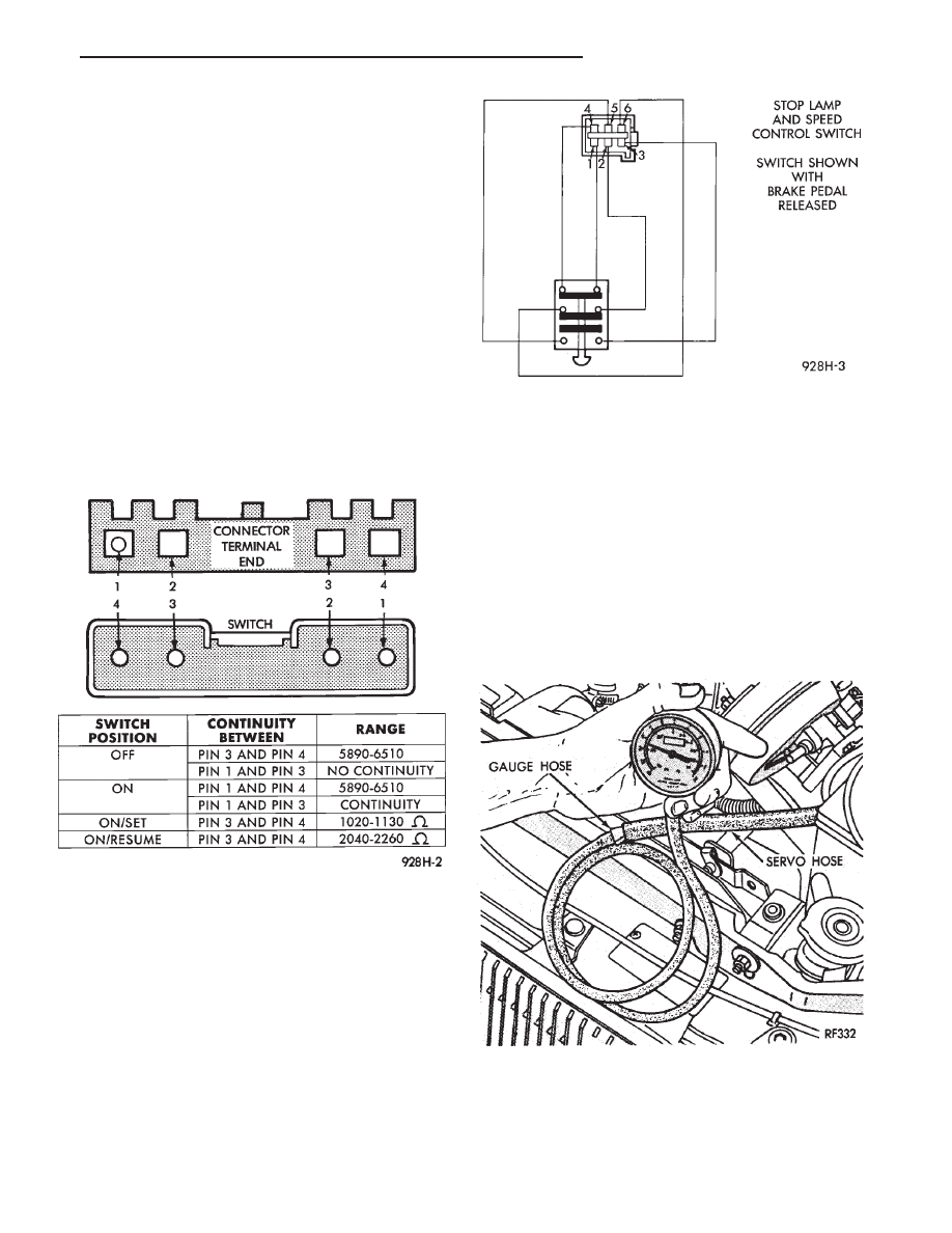
(2) Using an ohmmeter, test continuity at the four

pins of the speed control switch. Refer to Speed Control
Switch Continuity (Fig. 9).

(3) If there is no continuity or incorrect continuity at

any one of the switch positions, replace the switch.

STOP LAMP SPEED CONTROL SWITCH TEST

(1) Disconnect the six way connector at the stop

lamp switch (Fig. 10). Using an ohmmeter, continuity
may be checked at the switch side of the connector as
follows:

(a) With brake pedal released, there should be

continuity:

• Between pin 1 and pin 4.

• Between pin 3 and pin 6.

• No continuity between pin 2 and pin 5.

(b) With brake pedal depressed, there should be no

continuity:

• Between pin 1 and pin 4.

• Between pin 3 and pin 6.

• Continuity between pin 2 and pin 5.

(2) If the above results are not obtained, the stop

lamp switch is defective or out of adjustment.

(3) Stop lamp switch adjustment is detailed in

Group 5, Brakes.

VACUUM SUPPLY TEST

(1) Disconnect vacuum hose at the servo and install

a vacuum gauge in the hose (Fig. 11).

(2) Start engine and observe gauge at idle. Vacuum

gauge should read at least ten inches of mercury. Shut
off engine, the vacuum should continue to hold 10
inches of mercury.

Fig. 9 Speed Control Switch Continuity

Fig. 10 Stop Lamp and Speed Control Switch Wiring

Fig. 11 Vacuum Gauge Test

.

SPEED CONTROL SYSTEM

8H - 7

(3) If vacuum does not meet this requirement, check

and correct the following vacuum leaks:
• Vacuum lines

• Check valve

• Vacuum reservoir

• Servo Vacuum, refer to Servo Vacuum Test

• Poor engine performance.

SERVO VACUUM TEST

(1) Remove the speed control cable at the throttle

body end.

(2) Disconnect the 4-way electrical connector and

the vacuum harness at the servo (Refer to Fig. 6).

(3) Connect battery voltage to pin 2 of the servo.
(4) Ground the remaining three servo pins 1, 3 and

4.

(5) Connect a hand held vacuum pump to the servo

vacuum nipple and apply 10 to 15 inches of vacuum.

(6) The cable should pull in and hold for as long as

vacuum is applied.

SERVO UNIT

REMOVAL

(1) Remove two nuts attaching speed control cable

and mounting bracket to servo.

(2) Remove

screws

attaching

servo

mounting

bracket.

(3) Remove servo mounting bracket.
(4) Disconnect electrical connectors and vacuum

hose.

(5) Pull cable away from servo to expose retaining

clip and remove clip attaching cable to servo.

INSTALLATION

(1) With throttle in full open position align hole in

speed control cable sleeve with hole in servo pin and
install retaining clip.

(2) Connect vacuum hose to servo.
(3) Connect electrical connector.
(4) Position mounting bracket and install screws

attaching bracket. Tighten screws to 12 N

Im (105 in.

lbs.), if mounted to shock tower 5 N

Im (45 in. lbs.).

(5) Insert servo studs through holes in speed control

cable and mounting bracket.

(6) Install nuts, tighten to 7 N

Im (60 in. lbs.).

SPEED CONTROL SWITCH

The speed control switch is mounted in the steering

wheel and wired through the clock spring device under
the steering wheel hub (Fig.1).

WARNING: IF REMOVAL OF AIR BAG MODULE IS

NECESSARY, REFER TO GROUP 8M, RESTRAINT
SYSTEMS.

REMOVAL

(1) Turn off ignition.
(2) Remove two (2) screws from back side of steering

wheel.

(3) Rock switch away from air bag or horn pad while

lifting switch out of steering wheel.

(4) Disconnect 4-way electrical connector.

INSTALLATION

(1) Turn off ignition.
(2) Connect 4-way electrical connector from clock

spring to switch.

(3) Place switch in steering wheel, sliding the for-

ward edge of switch under air bag or horn pad. Line up
locating pins on switch with holes in steering wheel
frame.

(4) Attach switch to wheel with two screws starting

with the screw at the left end of the switch.

8H - 8

SPEED CONTROL SYSTEM

.

TURN SIGNALS AND HAZARD WARNING FLASHER

CONTENTS

page

page

CHIME FUNCTION . . . . . . . . . . . . . . . . . . . . . . . . 1
ELECTRONIC COMBINATION FLASHER

. . . . . . . 1

FLASHER SYSTEM DIAGNOSIS

. . . . . . . . . . . . . 3

GENERAL INFORMATION

. . . . . . . . . . . . . . . . . . 1

HAZARD WARNING SWITCH

. . . . . . . . . . . . . . . 1

MULTI-FUNCTION SWITCH

. . . . . . . . . . . . . . . . 1

GENERAL INFORMATION

WARNING: ON VEHICLES EQUIPPED WITH AIRBAG,
SEE GROUP 8M, RESTRAINT SYSTEMS FOR AIRBAG
REMOVAL PROCEDURES.

The turn signals are apart of the multi-function

switch. The switch contains the turn signal, headlamp
beam select, headlamp optical horn, windshield wiper,
pulse wipe and windshield washer controls. The inte-
grated switch is mounted on the left side of the steering
column. The driver moves the lever upward for the
right signal and downward for the left signal to flash.
After completion of a turn the system is canceled
automatically.

If only momentary signaling such as indication of a

lane change is desired, the switch is actuated to a left
or right intermediate detent position. In this position
the signal lamps flash as described above, but the
switch returns to the OFF position as the lever is
released.

Activate the system and the indicator lamps will

flash in unison with the turn signal lamps. This shows
that the system is operating.

HAZARD WARNING SWITCH

Refer to Group 8E, Instrument Panel, Headlamp

Switch.

CHIME FUNCTION

The chime will sound after the vehicle has traveled a

distance of 0.6 miles at a speed above 15 miles per
hour.

MULTI-FUNCTION SWITCH

The multi-function switch contains:

• Electrical circuitry for turn signal

• Headlamp beam select

• Headlamp optical horn

• Windshield wiper

• Pulse wipe

• Windshield washer switching

This integrated switch assembly is mounted to the

left hand side of the steering column. If any function of
the switch fails, the entire switch assembly must be
replaced. Refer to Fig. 1 for diagnosis.

SWITCH TEST

(1) Disconnect the negative battery cable.
(2) Remove the upper and lower column covers to

gain access to the switch connector.

(3) Remove switch connector.
(4) Using an ohmmeter, test for continuity between

the terminals of the switch as shown in the following
continuity charts (Fig 2 and 3).

(5) If reading are incorrect, replace switch.

REMOVAL

(1) Disconnect battery negative cable.
(2) Tilt column only remove tilt lever.
(3) Remove both upper and lower steering column

covers.

(4) Remove multi-function switch tamper proof

mounting screws (Fig.4).

(5) Gently pull switch away from column and loosen

connector screw. The screw will remain in the connec-
tor.

(6) Remove wiring connector from multi-function

switch.

INSTALLATION

(1) Install wiring connector to switch and tighten

connector retaining screw to 2 N

Im (17 in. lbs.) torque.

(2) Mount multi-function switch to column and

tighten retaining screws to 2 N

Im (17 in. lbs.) torque.

(3) Install steering column covers. Tighten retaining

screws to 2 N

Im (17 in. lbs.) torque.

(4) Tilt column only, install the tilt lever.
(5) Connect battery negative cable.
(6) Check the switch functions for proper operation.

ELECTRONIC COMBINATION FLASHER

The module provides both turn signal and hazard

flasher operation. The flasher plugs into the lower left
corner of relay bank to the left of the fuse block. To gain
access to the flasher, remove the lower steering column
cover. The flash rate for the turn signal and hazard
warning flasher is constant for any number of lamps.
Depending on exact current draw of lamps, there
should be between 60 and 120 flashes per minute. If a
lamp or circuit to a lamp is open, the

.

TURN SIGNALS AND HAZARD WARNING FLASHER

8J - 1

Fig. 1 Turn Signal and Hazard Warning Flasher Diagnosis

8J - 2

TURN SIGNALS AND HAZARD WARNING FLASHER

.


Content   ..  216  217  218  219   ..