Chrysler Town & Country/Voyager, Dodge Caravan, Plymouth Voyager. Manual - part 217
 

  Index      Chrysler     Chrysler Town & Country/Voyager, Dodge Caravan, Plymouth Voyager - service repair manual 1992 year


Search            


Content   ..  215  216  217  218   ..


Chrysler Town & Country/Voyager, Dodge Caravan, Plymouth Voyager. Manual - part 217


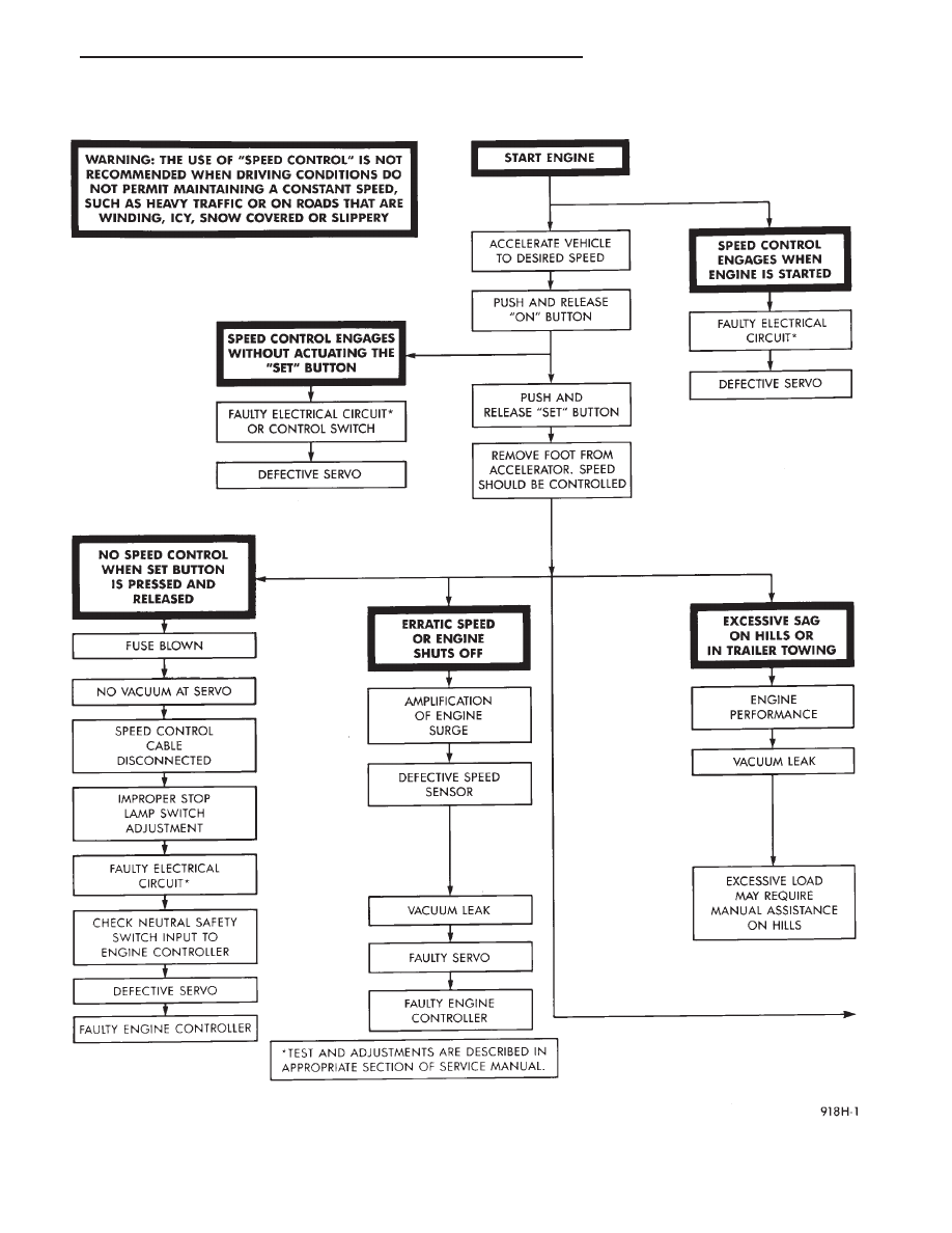
SYSTEM DIAGNOSIS

.

SPEED CONTROL SYSTEM

8H - 3

SYSTEM DIAGNOSIS—CONTINUED

8H - 4

SPEED CONTROL SYSTEM

.

(b) Plug DRB II into the diagnostic connector in

the engine compartment.

(c) Check that either a Fault Code 34 or Fault

Code 15 is shown.

(d) An inoperative speed control may still occur

without either fault code being shown.

(e) With key inserted in ignition switch, cycle

switch to ON position three times. On third cycle,
leave switch in ON position.

(f) After switch has been cycled three times, ob-

serve CHECK ENGINE indicator on instrument
cluster. If a Fault Code is present, the indicator will
flash (blink) in a series and will show which Fault
Code is the problem. EXAMPLE: A series of three
flashes in rapid succession, a slight pause, then four
flashes in rapid succession would show a Fault Code
34.
(2) If no Fault Code appears, or Fault Code 34 is

observed, refer to:
• The Servo Electrical Test.

• The Engine Controller Electrical Test.

(3) If a fault code 15 is observed, test distance sensor.
For testing distance sensor and related components

refer to the Powertrain Diagnostics Test Procedure
Manual.

(4) Correct any problems found when performing

these tests and recheck for Fault Code if changes were
made.

(5) If no problems were found above, replace engine

controller.

ELECTRICAL TEST:

Electronic speed control systems may be tested using

two different methods. One involves use of a DRB II. If
this test method is desired, please refer to the Power-

train Diagnostic Test Procedures for charging and
speed control system manual.

The other test method uses a volt/ohm meter and is

described in the following tests.

If any information is needed concerning wiring, refer

to Group 8W, Wiring Diagrams.

CAUTION: When test probing for voltage or continu-
ity at electrical connectors, care must be taken not to
damage connector, terminals, or seals. If these com-
ponents are damaged, intermittent or complete sys-
tem failure may occur.

SERVO ELECTRICAL TESTS

WARNING: ON VEHICLES EQUIPPED WITH AIRBAG,
SEE GROUP 8M, RESTRAINT SYSTEMS FOR AIR-
BAG, STEERING WHEEL OR COLUMN REMOVAL
PROCEDURES.

(1) Turn ignition switch to the ON position. With the

speed control switch in the ON position, set up a
voltmeter to read battery voltage and connect the
negative lead to a good chassis ground.

(2) Disconnect the four-way connector going to the

servo (Fig. 6). Test pin 2 of the main harness four-way
connector for battery voltage. If not OK go to step 3. If
voltage is OK go to step 4.

(3) Perform the following tests.

(a) Disconnect the six-way connector at the stop

lamp switch and test pin 1 of the main harness for
battery voltage. If voltage is OK perform the stop
lamp switch test.

(b) If the stop lamp switch tests OK; repair wire

between the servo and the stop lamp switch.

(c) If no voltage at pin 1 at the 6-way stop lamp

connector, remove the speed control switch and dis-

Fig. 5 Speed Control Circuit

Fig. 6 Servo Harness Connector

.

SPEED CONTROL SYSTEM

8H - 5

connect the four-way connector. Test pin 1 of main
harness for battery voltage.

(d) If voltage is OK perform the speed control

switch test.

(e) If speed control switch is OK, test continuity

across the clockspring.

(f) If clockspring OK, repair as required, wire be-

tween stop lamp switch and clockspring.

(g) If no voltage at pin 1 of the 4-way speed con-

trol switch connector.

• Test for battery voltage between the ignition and
the fuse
• If voltage OK, check fuse

• If fuse OK, repair wire between fuse and clock-
spring

(4) Connect a jumper wire between pin 2 of the

four-way servo connector of the main harness and
pin 2 of the speed control servo (Fig. 6). The other
three pins from the servo should show battery volt-
age. If not, replace the servo.

(5) Using an ohmmeter, connect one lead to a good

body ground. With the other lead touch pin 1 in the
four-way servo connector of the main harness.The
meter should show continuity. If not, repair the
ground circuit as necessary.

ENGINE CONTROLLER ELECTRICAL TEST

WARNING: ON VEHICLES EQUIPPED WITH AIR-
BAG, SEE GROUP 8M, RESTRAINT SYSTEMS FOR
AIRBAG,

STEERING

WHEEL

OR

COLUMN

RE-

MOVAL PROCEDURES.

(1) Unplug 60-way connector from the engine con-

troller, located next to the battery (Fig. 7).

(2) Remove speed control switch. Refer to Speed

Control Switch Removal. Disconnect the 4-way con-
nector.

(3) Using an ohmmeter test continuity between pin

23 of engine controller and pin 4 of the speed control
switch harness. Refer to Fig. 8 for controller terminal
locations.

(a) If no continuity, repair wire circuit as neces-

sary.

(b) Continuity OK, refer to Speed Control Switch

Test.
(4) Connect the 4-way connector to speed control

switch.

(5) Connect negative lead of voltmeter to a good

body ground near the engine controller.

(6) Turn ignition switch ON.
(7) Place speed control switch in the OFF position.

Touch the positive lead of the voltmeter to pin 53,
the voltmeter should read 0 volts.

(8) Place speed control switch in the ON position.

Touch the positive lead of the voltmeter to pin 53,
the voltmeter should read battery voltage.

(9) If no voltage, repair the wire between pin 53

and pin 3 of the speed control servo (Fig. 6). If volt-
age is OK go to step 8.

(10) Place speed control switch in the OFF posi-

tion. Touch the positive lead of the voltmeter to pin
33, voltmeter should read 0 volts.

(11) Place speed control switch in the ON position.

Touch the positive lead of the voltmeter to pin 33,
the voltmeter should read battery voltage.

(12) If no voltage, repair the wire between pin 33

and pin 4 of the speed control servo (Fig. 6). If volt-
age is OK go to step 11.

(13) Using an ohmmeter, connect one lead to a

good body ground and touch the other lead to pin 29.
With the brake pedal released, the meter should
show continuity. When the pedal is depressed, the
meter should show no continuity. If no continuity
perform the following test:

(a) Using an ohmmeter test continuity between

pin 29 of engine controller and pin 3 of the stop
lamp switch connector.

(b) If no continuity, repair as necessary.

Fig. 7 Engine Controller and Connector Location

Fig. 8 Engine Controller 60-Way Connector Shown

from Terminal End

8H - 6

SPEED CONTROL SYSTEM

.


Content   ..  215  216  217  218   ..