Chrysler Town & Country/Voyager, Dodge Caravan, Plymouth Voyager. Manual - part 216


  Index      Chrysler     Chrysler Town & Country/Voyager, Dodge Caravan, Plymouth Voyager - service repair manual 1992 year


Search            


Content   ..  214  215  216  217   ..


Chrysler Town & Country/Voyager, Dodge Caravan, Plymouth Voyager. Manual - part 216


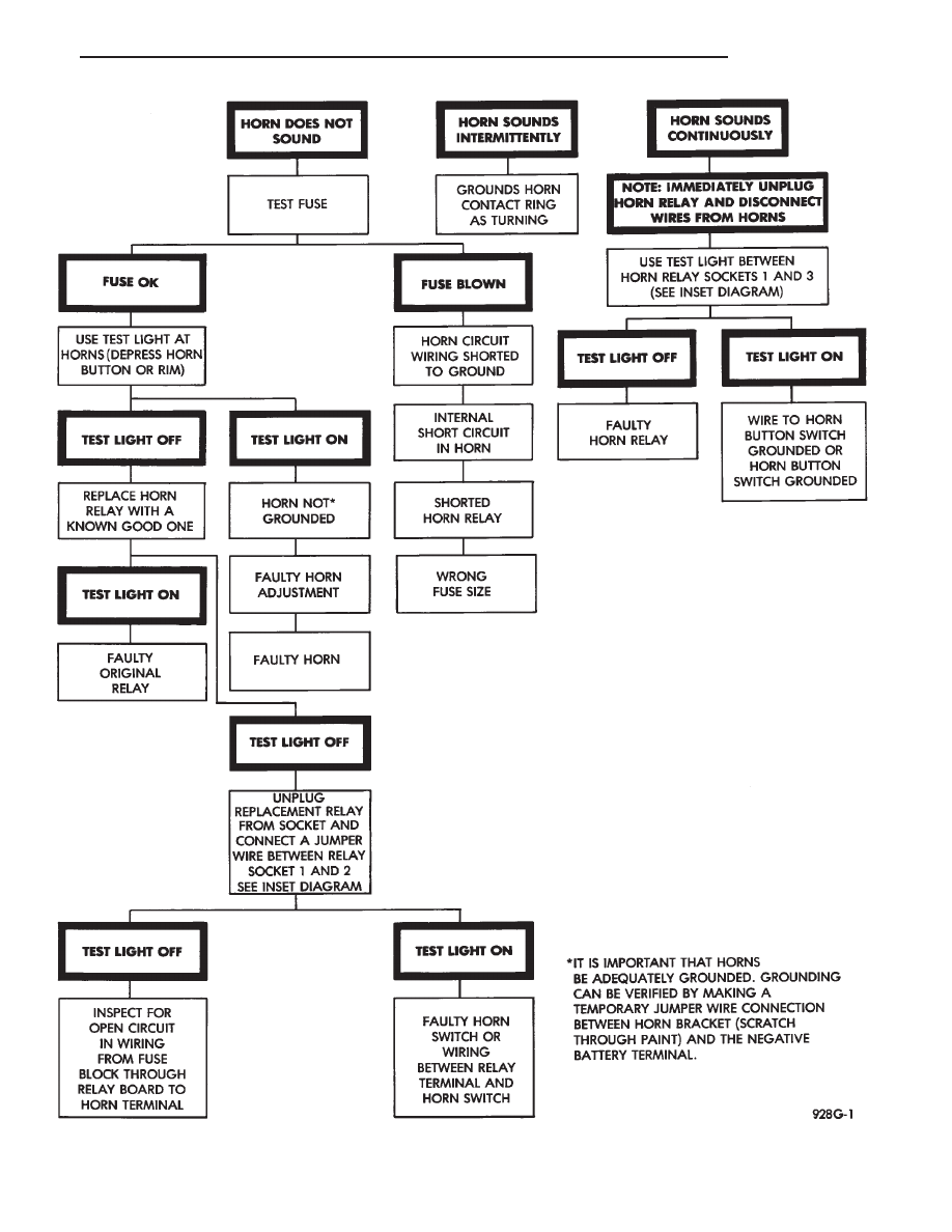
Fig. 5 Horn Diagnosis

.

HORNS

8G - 3

Fig. 8 Standard Steering Wheel

Fig. 6 High Line Steering Wheel

Fig. 7 Low Line Steering Wheel

8G - 4

HORNS

.

SPEED CONTROL SYSTEM

CONTENTS

page

page

CHECKING FOR FAULT CODE . . . . . . . . . . . . . . . 2
DIAGNOSIS PROCEDURES

. . . . . . . . . . . . . . . . . 2

ELECTRICAL TEST:

. . . . . . . . . . . . . . . . . . . . . . . 5

ENGINE CONTROLLER ELECTRICAL TEST . . . . . 6
GENERAL INFORMATION

. . . . . . . . . . . . . . . . . . 1

INOPERATIVE SYSTEM . . . . . . . . . . . . . . . . . . . . 2
ROAD TEST . . . . . . . . . . . . . . . . . . . . . . . . . . . . . 2

SERVO ELECTRICAL TESTS

. . . . . . . . . . . . . . . . 5

SERVO UNIT

. . . . . . . . . . . . . . . . . . . . . . . . . . . . 8

SERVO VACUUM TEST

. . . . . . . . . . . . . . . . . . . . 8

SPEED CONTROL SWITCH

. . . . . . . . . . . . . . . . . 8

SPEED CONTROL SWITCH TEST

. . . . . . . . . . . . 7

STOP LAMP SPEED CONTROL SWITCH TEST

7

VACUUM SUPPLY TEST

. . . . . . . . . . . . . . . . . . . 7

GENERAL INFORMATION

The speed control system is electronically controlled

and vacuum operated. The electronic control is inte-
grated into the engine controller, located next to bat-
tery. The controls are located on the steering wheel and
consist

of

the

ON/OFF,

RESUME/ACCEL

and

SET/DECEL buttons (Fig.1). For identification and
location of the major components (Fig. 2 through 4).

The system is designed to operate at speeds above 35

mph (50 km/h).

WARNING: THE USE OF SPEED CONTROL IS NOT
RECOMMENDED WHEN DRIVING CONDITIONS DO
NOT PERMIT MAINTAINING A CONSTANT SPEED,
SUCH AS IN HEAVY TRAFFIC OR ON ROADS THAT
ARE WINDING, ICY, SNOW COVERED, OR SLIPPERY.

TO ACTIVATE:
the ON/OFF button to the depressed latched posi-

tion, ON, the speed control function is now ready for
use.

TO DEACTIVATE:
A soft tap of the brake pedal, normal brake applica-

tion or depressing the clutch pedal while the system is
engaged will disengage speed control without erasing
memory. A sudden increase in engine rpm may be
experienced if the clutch pedal is depressed while the
speed control system is engaged. Pushing the ON/OFF
button to the unlatched position or turning off the
ignition erases the memory.

TO SET SPEED:
When the vehicle has reached the desired speed push

the SET/DECEL button to engage system which, will
then automatically maintain the desired speed.

TO DECELERATE:
When

speed

control

is

engaged,

holding

the

SET/DECEL button depressed allows the vehicle to
coast to a lower speed setting.

Fig. 1 Speed Control Switch

Fig. 2 Speed Control System—2.2L and 2.5L

.

SPEED CONTROL SYSTEM

8H - 1

TO RESUME:
After disengaging the speed control system by tap-

ping the brake pedal or clutch pedal, push the
RESUME/ACCEL button to return vehicle to the pre-
viously set speed.

TO ACCELERATE:
While

speed

control

is

engaged,

hold

the

RESUME/ACCEL button depressed and release at a
new desired speed. This will allow the vehicle to
accelerate and set at a higher speed setting.

TAP-UP:
When the speed control system is engaged, tapping

the RESUME/ACCEL button will increase the speed
setting by 2 mph (3 km/h). The system will respond to
multiple tap-ups.

TO ACCELERATE for PASSING:
Depress the accelerator as you would normally.

When the pedal is released the vehicle will return to
the speed setting in memory.

DIAGNOSIS PROCEDURES

Whenever a speed control malfunction occurs, first

verify that the speed control wire harness is properly
connected to all connectors before starting normal
diagnosis and repair procedures. Refer to Electronic
Speed Control System Diagnosis Chart or Speed Con-
trol Circuit (Fig. 5).

A poor connection can cause a complete or intermit-

tent malfunction and is also the only connection in the
circuit, that cannot be tested. For this reason, a loose
connection may be misdiagnosed as a component mal-
function.

Also, check all vacuum connections for tightness and

cracked hoses.

ROAD TEST

Road test vehicle to verify reports of speed control

system malfunction. The road test should include at-
tention to the speedometer. Speedometer operation
should be smooth and without flutter at all speeds.

Flutter in the speedometer shows a problem which,

might cause surging in the speed control system. The
cause of any speedometer deficiencies should be cor-
rected before proceeding.

INOPERATIVE SYSTEM

If road test verifies an inoperative system with a

correct speedometer operation:
• Inspect fuse

• Check for loose electrical and vacuum connections at
the servo
• Check for correct position of the vacuum check valve
in the hose from servo to vacuum source. The word
VAC on the valve must point toward the vacuum
source.
• Corrosion should be removed from electrical termi-
nals and a light coating of Mopar Multi-Purpose
Grease, or equivalent, applied.
• Inspection also should be made to verify that both
ends of the speed control cable are securely attached. If
either end is loose, the speed control system will be
inoperative.

CHECKING FOR FAULT CODE

(1) When trying to verify a speed control system

electronic malfunction:

(a) Connect a DRB II if available.

Fig. 3 Speed Control System—3.0L

Fig. 4 Speed Control System—3.3L

8H - 2

SPEED CONTROL SYSTEM

.


Content   ..  214  215  216  217   ..