Chrysler Town & Country/Voyager, Dodge Caravan, Plymouth Voyager. Manual - part 172


  Index      Chrysler     Chrysler Town & Country/Voyager, Dodge Caravan, Plymouth Voyager - service repair manual 1992 year


Search            


Content   ..  170  171  172  173   ..


Chrysler Town & Country/Voyager, Dodge Caravan, Plymouth Voyager. Manual - part 172


ABS BRAKING SYSTEM DIAGNOSIS

WARNING: SOME OPERATIONS IN THIS SECTION
REQUIRE THAT HYDRAULIC TUBES, HOSES AND
FITTINGS BE DISCONNECTED FOR INSPECTION OR
TESTING PURPOSES. THIS BRAKE SYSTEM USES A
HYDRAULIC ACCUMULATOR THAT, WHEN FULLY
CHARGED, CONTAINS BRAKE FLUID AT HIGH PRES-
SURE. BEFORE DISCONNECTING ANY HYDRAULIC
TUBE, HOSE OR FITTING. BE SURE THAT THE AC-
CUMULATOR IS FULLY DE-PRESSURIZED AS DE-
SCRIBED IN THIS SECTION. FAILURE TO DE-
PRESSURIZE THE ACCUMULATOR MAY RESULT IN
PERSONAL INJURY AND/OR DAMAGE TO PAINTED
SURFACES.

CAUTION: Certain components of the Anti-Lock
Brake System (ABS) are not intended to be serviced
individually. Attempting to remove or disconnect cer-
tain system components, may result in personal
injury and/or improper system operation. Only those
components with approved removal, service and in-
stallation procedures described in this manual
should be serviced.

GENERAL INFORMATION

This section contains information necessary for diag-

nosis of mechanical conditions that can affect the
operation of the Bendix Anti- Lock 10 Brake System.
Specifically, this section should be used to help diag-
nose mechanical conditions that result in any of the
following:

CAUTION: Review this entire section before perform-
ing any mechanical work on a vehicle equipped with
the Bendix Anti-Lock 10 brake system. For informa-
tion on precautions pertaining to potential compo-
nent damage, vehicle damage and personal injury.

(1) Anti-Lock warning lamp illuminated
(2) BRAKE warning lamp on
(3) Lack of Power Assist or Excessive Pedal Travel
(4) Brakes Lock on Hard Application
Diagnosis of conditions that are obviously mechani-

cal in nature. Such as brake noise, brake pulsation, or
vehicle vibration during normal braking. Should be
directed to Group 5 Brakes in the service manual. This
also pertains to problems involving the parking brake
system.

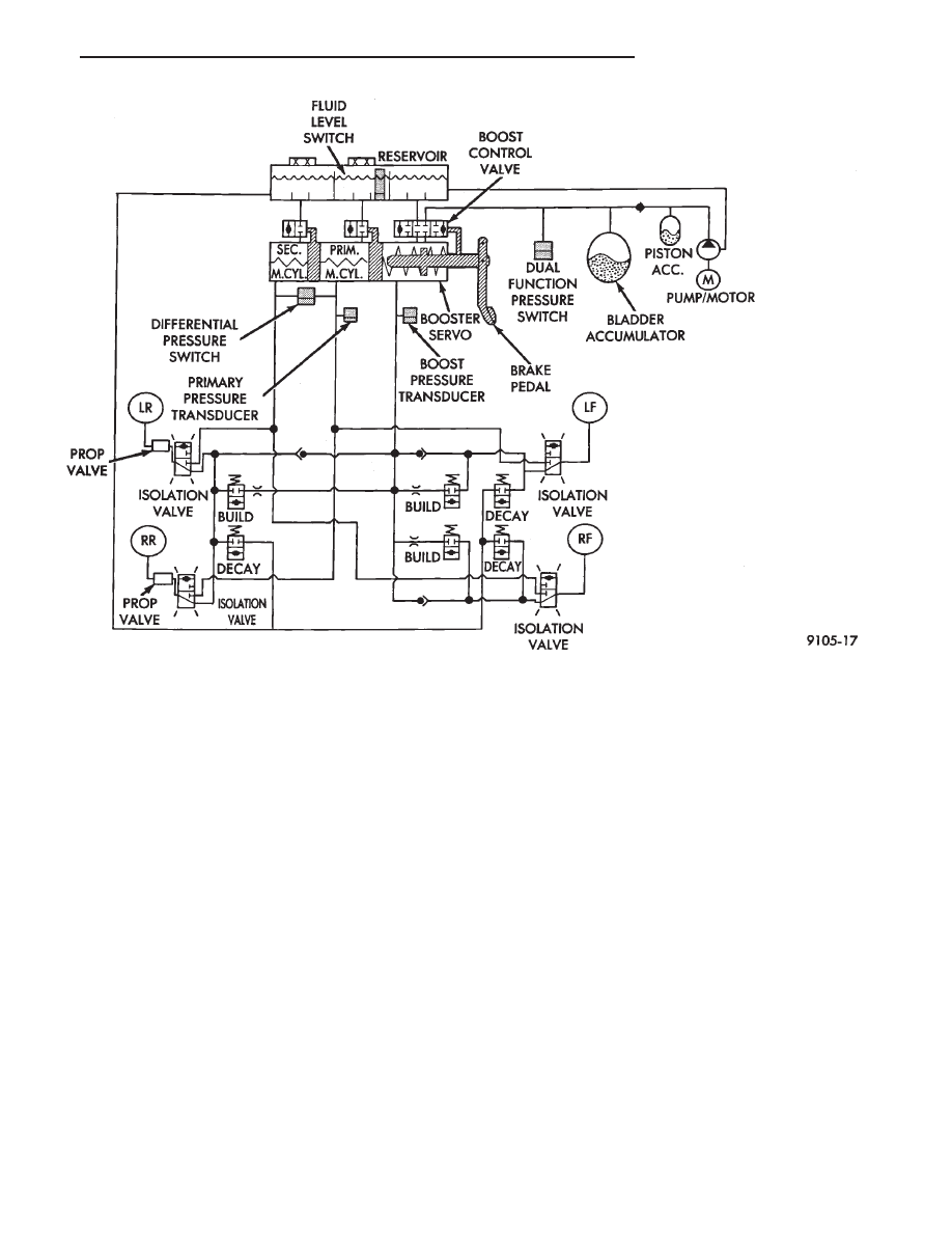
Fig. 12 Hold Pressure - Hydraulic Control

.

ANTI-LOCK BRAKES

5 - 71

In order to effectively diagnose an Anti-Lock Brake

System (ABS) condition. It is important to read Section
1 of this manual, Anti-Lock Brake System Description.
This section will give you information on the function
of the ABS components. Then follow the diagnostic
procedures outlined in this section.

Many conditions that generate customer complaints

may be normal operating conditions, but are judged to
be a problem due to unfamiliarity with the ABS sys-
tem. These conditions can be recognized without per-
forming extensive diagnostic work. Given adequate
understanding of the operating principles and perfor-
mance characteristics of the ABS system. See Section 1
of this manual to familiarize yourself with the operat-
ing principles of the ABS system.

DEFINITIONS

Several abbreviations are used in this manual. They

are presented here for reference.
• CAB—Controller Anti-Lock Brake

• ABS—Anti-Lock Brake System

• PSI—Pounds per Square Inch (pressure)

• WSS—Wheel Speed Sensor

ABS CONTROLLER ANTI-LOCK BRAKE (CAB) SER-
VICE PRECAUTIONS

The ABS system uses an electronic control module,

the (CAB). This module is designed to withstand nor-

mal current draws associated with vehicle operation.
However care must be taken to avoid overloading the
(CAB) circuits. In testing for open or short circuits, do
not ground or apply voltage to any of the circuits unless
instructed to do so by the appropriate diagnostic pro-
cedure. These circuits should only be tested using a
high impedance multi-meter, special tools or the DRB
II tester as described in this section. Power should
never be removed or applied to any control module with
the ignition in the ON position. Before removing or
connecting battery cables, fuses, or connectors, always
turn the ignition to the OFF position.

ABS SYSTEM GENERAL SERVICE PRECAUTIONS

TEST DRIVING ABS COMPLAINT VEHICLES

Most ABS complaints will require a test drive as a

part of the diagnostic procedure. The purpose of the
test drive is to duplicate the condition.

Before test driving a brake complaint vehicle,

especially if the Red Brake Warning Lamp is on,
test the brakes at low speed to be sure that the
car will stop normally. Remember that condi-
tions that result in illumination of the Red Brake
Warning Lamp may indicate reduced braking
ability. The following procedure should be used
to test drive an ABS complaint:

Fig. 13 Decay Pressure - Hydraulic Control

5 - 72

ANTI-LOCK BRAKES

.

(1) Ignition on. Turn the ignition to the ON position

without starting the car and wait until the Red Brake
Warning Lamp and Amber Anti-Lock Warning Lamp
turn off. This will allow the pump to charge the
accumulator to operating pressure. If the warning
lamp(s) do not turn off, go to step 3.

(2) Ignition off for 15 seconds.
(3) Start car. Wait for displays to return to normal

operating mode before proceeding.

(4) With Shift lever in PARK, slowly depress brake

pedal and release.

(5) Drive vehicle a short distance. During this test

drive, be sure that the vehicle achieves at least 20 mph.
Then brake to at least one complete stop and accelerate
slowly back up to at least 20 mph.

(6) If a functional problem with the A.B.S. system is

determined while test driving a vehicle. Refer to the
Bendix Anti-Lock 10 Diagnostics Manual for required
test procedures and proper use of the DRB II tester.

CAUTION: The following are general precautions that
should be observed when servicing and diagnosing
the ABS system and/or other vehicle systems. Failure
to observe these precautions may result in ABS
system damage.

(1) If welding work is to be performed on the vehicle

using an arc welder, the (CAB) should be disconnected
before the welding operation begins.

(2) The (CAB) and hydraulic assembly 10 way con-

nectors should never be connected or disconnected with
the ignition on.

(3) Some components of the ABS system are not

serviced separately and must be serviced as complete
assemblies. Do not disassemble any component which
is designated as non-serviceable.

(4) Always de-pressurize the Hydraulic Accu-

mulator when performing any work that re-
quires disconnecting any hydraulic tube, flex
hose or fitting. The ABS system uses brake fluid
at high pressure. Failure to de-pressurize the
accumulator may result in personal injury
and/or damage to painted surfaces.

Brake fluid will damage painted surfaces. If brake

fluid is spilled on any painted surfaces, wash off with
water immediately.

DE-PRESSURIZING HYDRAULIC ACCUMULA-
TOR

The ABS pump/motor assembly keeps the hydraulic

accumulator charged between approximately 11,032
and 13,790 kPa (1600 and 2000 psi) anytime the
ignition is in the ON position. The pump/motor assem-
bly cannot run if the ignition is off or if either battery
cable is disconnected.

Unless otherwise specified, the hydraulic accumula-

tor should be de-pressurized before disassembling any

portion of the hydraulic system. The following proce-
dure should be used to de-pressurize the hydraulic
accumulator:

(1) With ignition off, or either battery cable discon-

nected, pump the brake pedal a minimum of 40 times
using approximately 50 pounds of pedal force. A notice-
able change in pedal feel will occur when the accumu-
lator becomes discharged.

(2) When a definite increase in pedal effort is felt,

pump the pedal a few additional times. This will insure
removal of all hydraulic pressure from the brake sys-
tem.

WHEEL SPEED SENSOR CABLES

Proper installation of wheel speed sensor cables is

critical to continued ABS system operation. Be sure
that cables are installed and routed properly. Failure to
install cables in their retainers, as shown in Section 3
of this manual. May result in contact with moving
parts or over extension of cables, resulting in an open
circuit.

MECHANICAL DIAGNOSTICS AND SERVICE PRO-
CEDURES

SPECIAL SERVICE TOOLS

Some diagnostic procedures in this section require

the use of special service tools. Each of these tools is
described below.

DRB II DIAGNOSTIC TESTER

Some of the diagnostic procedures that are explained

in this section require the use of the DRB II DIAG-
NOSTICS TESTER to insure that proper diagnostics
are performed. Refer to those sections for proper test-
ing procedures and the DRB II manual for its proper
operational information.

MST-6163 PRESSURE TESTER

Some diagnostic procedures in this manual require

the use of the MST-6163 pressure gauge and adaptor
(Fig. 1) to measure accumulator pressure during cer-
tain phases of operation. The pressure gauge and
adaptor should be installed as follows:

(1) De-pressurize the accumulator by pumping the

brake pedal a minimum of 40 times with the ignition
off. The procedure is fully explained under De-
Pressurizing Hydraulic Accumulator which is de-
scribed earlier in this System Diagnosis Section.

WARNING: FAILURE TO DE-PRESSURIZE THE AC-
CUMULATOR PRIOR TO PERFORMING THIS OPERA-
TION MAY RESULT IN PERSONAL INJURY AND/OR
DAMAGE TO PAINTED SURFACES.

(2) Remove hydraulic assembly accumulator port

plug,located on right hand side of hydraulic assembly
(Fig. 1).

.

ANTI-LOCK BRAKES

5 - 73

(3) Install pressure gauge to hydraulic assembly

adaptor (Fig. 2) into accumulator port of hydraulic
assembly, and tighten to 10 N

Im (7.5 ft. lbs.) torque.

(4) Install adaptor onto the pressure gauge hose

(Fig. 2) and tighten the fitting to 15 N

Im (11 ft. lbs.)

torque.

(5) Install pressure gauge and hose adaptor assem-

bly onto the adaptor installed in the hydraulic assem-
bly accumulator port. Then install the retaining clip
into the grove on the accumulator port adaptor (Fig. 2).
MAKE SURE THAT THE RETAINING CLIP IS
INSTALLED ON THE ACCUMULATOR PORT
ADAPTOR BEFORE RE-PRESSURIZING THE
HYDRAULIC SYSTEM.

WARNING: BEFORE REMOVING PRESSURE GAUGE
AND ADAPTOR, BE SURE TO DE-PRESSURIZE THE
HYDRAULIC

ASSEMBLY.

THEN

INSTALL

AND

TIGHTEN ACCUMULATOR PORT PLUG TO 12 N

I

M (9

FT. LBS.).

It is not necessary to bleed the hydraulic assembly or

brake system after installation and removal of the
pressure gauge. Unless additional tubes, hoses, or
fittings were removed or loosened.

INTERMITTENT FAULTS

As with almost any electronic system, intermittent

faults in the ABS system may be difficult to accurately
diagnose.

Most intermittent faults are caused by faulty electri-

cal connections or wiring. When an intermittent fault
is encountered, check suspect circuits for:

(1) Poor mating of electrical connector halves, or

electrical terminals not fully seated in the connector
body.

(2) Improperly formed or damaged electrical termi-

nals. All connector terminals in a suspect circuit should
be carefully reformed to increase contact tension.

(3) Poor terminal to wire connection. This requires

removing the terminal from the connector body and
inspecting for proper terminal to wire connection.

If a visual check does not find the cause of the

problem, operate the vehicle in an attempt to duplicate
the condition and record the Fault Code.

Most failures of the ABS system will disable the

Anti-Lock function for the entire ignition cycle even if
the fault clears before ignition key-off. There are some
failure conditions however, which will allow ABS op-
eration to resume during the ignition cycle in which a
failure occurred. If the failure conditions are no longer
present.

The following conditions may result in intermittent

illumination of the Red Brake Warning Lamp and/or
Amber Anti-Lock Warning Lamp. All other failures will
cause the lamp(s) to remain on until the ignition switch
is turned off. Circuits and or components involving
these inputs to the (CAB) should be investigated if a
complaint of intermittent warning system operation is
encountered.

Fig. 1 Hydraulic Assembly Accumulator Port Plug

Location

Fig. 2 Pressure Gauge and Adapter Installed on Hy-

draulic Assembly

5 - 74

ANTI-LOCK BRAKES

.


Content   ..  170  171  172  173   ..