Chrysler Town & Country/Voyager, Dodge Caravan, Plymouth Voyager. Manual - part 171
ANTI-LOCK SYSTEM RELAYS AND WARNING
LAMPS
PUMP/MOTOR RELAY
Pump/Motor power is supplied by the Pump/Motor
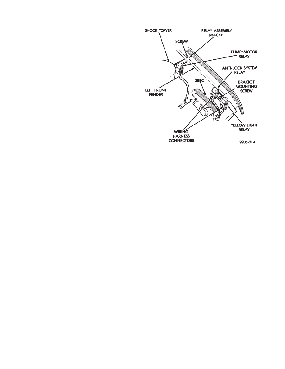
Relay. The Pump/Motor relay is located in front of the
left shock tower (Fig. 9). The relay coil is energized by
a ground from the Dual Function Pressure Switch.
SYSTEM RELAY
The (ABS) Modulator Valves and Anti-Lock Warning
Lamp Relay are controlled through a System Relay.
The System relay is located on the top left inner fender
behind the headlight (Fig. 9). The system relay pro-
vides power to the (CAB) for modulator valve operation
(pins 47 and 50) after the start-up cycle when the
ignition is turned on.
ANTI-LOCK WARNING LAMP RELAY
The Anti-Lock Warning Lamp is controlled by the
Yellow Light Relay. See (Fig. 9) for location behind the
left headlight. With the relay de-energized, the lamp is
lit. When the system relay is energized by the (CAB),
the Anti-Lock Warning Lamp relay is energized, and
the lamp is turned off. Thus, the lamp will be lit if the
(CAB) is disconnected or if a system fault causes (ABS)
function to be turned off, or if the system relay fails
open.
ANTI-LOCK WARNING LAMP OFF
System Relay (normally open) and Yellow Light
Relay (normally closed) Energized.
From pin 57 the (CAB) energizes the system relay
coil. The current flow in the coil closes the system relay.
Current is then provided to pins 47 and 50 of the (CAB)
to provide power to the modulator valves. This current
also energizes the Yellow Light Relay coil. The current
flow in the yellow light relay coil opens the Anti-Lock
Warning Lamp Relay Switch. This breaks the ground
path to the Anti-Lock Warning Lamp and the lamp is
turned off.
The (CAB) by itself, also can turn on the Anti-Lock
Warning Lamp. The (CAB) can turn on the Anti-Lock
Warning Lamp by providing a ground at pin 15.
ANTI-LOCK WARNING LAMP ON
System Relay and Anti-Lock Warning Lamp
Relay De-Energized.
When the Amber Anti-Lock Warning Lamp is on,
there is no current flow from the (CAB) at pin 57. The
system relay coil is NOT energized. No current flows to
pins 47 and 50 (modulator valve power), or to the
Anti-Lock Warning Lamp relay coil. Thus, the Anti-
Lock Warning Lamp Relay is not energized. The Anti-
Lock Warning Lamp is grounded through the Anti-
Lock Warning Lamp relay contacts. The Anti-Lock
Warning Lamp is illuminated.
Fig. 9 Pump/Motor and Anti-Lock System Relays
.
ANTI-LOCK BRAKES
5 - 67