Chrysler Town & Country/Voyager, Dodge Caravan, Plymouth Voyager. Manual - part 166
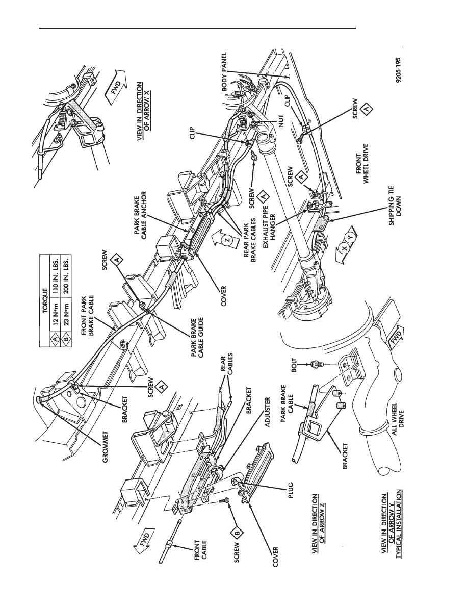
Fig.
1
Parking
Brake
Cable
Routing
F
.W
.D.
&
A.W
.D.
.
BRAKES
5 - 47
Index Chrysler Chrysler Town & Country/Voyager, Dodge Caravan, Plymouth Voyager - service repair manual 1992 year
|
|
|
Fig. 1 Parking Brake Cable Routing F .W .D. & A.W .D. . BRAKES 5 - 47 |