Chrysler Town & Country/Voyager, Dodge Caravan, Plymouth Voyager. Manual - part 164


  Index      Chrysler     Chrysler Town & Country/Voyager, Dodge Caravan, Plymouth Voyager - service repair manual 1992 year


Search            


Content   ..  162  163  164  165   ..


Chrysler Town & Country/Voyager, Dodge Caravan, Plymouth Voyager. Manual - part 164


CLEANING AND INSPECTION

Clean all parts using alcohol or a suitable solvent

and wipe dry. Clean out all drilled passages and bores.
(Whenever a caliper has been disassembled, a
new boot and seal must be installed at assembly).

Inspect the piston bore for scoring or pitting. Bores

that show light scratches or corrosion, can usually be
cleared with crocus cloth.

Bores that have deep scratches or scoring should be

honed. Use Caliper Hone, Special Tool C-4095, or
equivalent providing the diameter of the bore is not
increased more than 0.0254 mm (0.001 inch) (Fig. 5).

If the bore does not clean up within this specification,

a new caliper housing should be installed. Install a new
piston if the old one is pitted or scored.

When using Caliper Honing Tool, Special Tool

C-4095, coat the stones and bore with brake fluid.
After honing the bore, carefully clean the seal
and boot grooves with a stiff non-metallic rotary
brush.

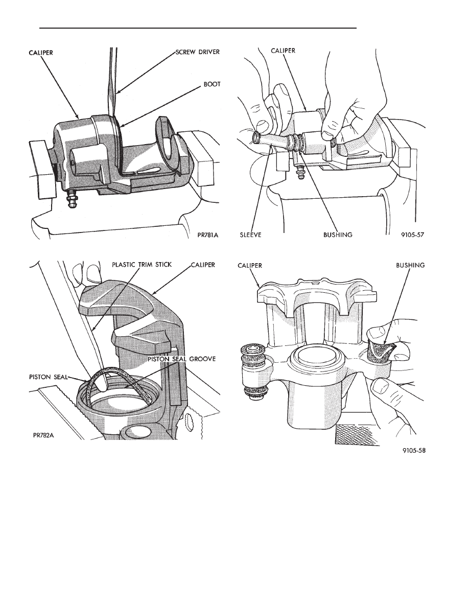
Fig. 1 Removing Piston Dust Boot

Fig. 2 Removing Piston Seal

Fig. 3 Removing Inner Sleeve

Fig. 4 Removing Bushings From Caliper

.

BRAKES

5 - 39

Use extreme care in cleaning the caliper after

honing. Remove all dirt and grit by flushing the
caliper with brake fluid; wipe dry with a clean,
lint free cloth and then clean a second time.

ASSEMBLING CALIPER

Clamp caliper in vise (with protective caps on vise

jaws).

CAUTION: Excessive vise pressure will cause bore
distortion and binding of piston.

Dip new piston seal in clean brake fluid and install in

the groove of the caliper bore. Seal should be positioned
at one area in groove and gently worked around the
groove (Fig. 1), using only your fingers until properly
seated.

NEVER USE AN OLD PISTON SEAL. (Be sure

that fingers are clean and seal is not twisted or rolled)
(Fig. 1).

Coat new piston boot with clean brake fluid leaving a

generous amount inside boot.

Position dust boot over piston after coating with

brake fluid.

Install piston into caliper bore pushing it past the

piston seal until it bottoms in the caliper bore (Fig. 2).

CAUTION: Force must be applied to the piston uni-
formly to avoid cocking and binding of the piston in
the bore of the caliper.

Fig. 5 Honing Piston Bore

Fig. 1 Installing New Piston Seal

Fig. 3 Installing Dust Boot in Caliper Counterbore

Fig. 2 Pushing Piston into Bore

5 - 40

BRAKES

.

Position dust boot in counterbore of the caliper piston

bore.

Using a hammer and Installer Piston Caliper Boot,

Special Tool C-4689 and Handle, Special Tool C-4171,
drive boot into counterbore of the caliper (Fig. 3).

Use the following steps, to install the Guide Pin

Sleeve Bushings into the caliper assembly.

(1) Fold the bushing in half lengthwise at the solid

middle section of the bushing (Fig. 4).

(2) Using your fingers insert the folded bushing into

the caliper assembly (Fig. 5). Do not use a sharp
object to perform this step do to possible damage
to the bushing.

(3) Unfold the bushing using your fingers or a

wooden dowel until the bushing is fully seated into the

caliper assembly. Flanges should be seated evenly on
both sides of the bushing hole in the caliper assembly
(Fig. 6).

Install the Guide Pin Sleeve into the guide bushing

using the following procedure.

(1) Install the sleeve into one end of the bushing

until the seal area of the bushing is past the seal groove
in the sleeve (Fig. 7).

(2) Holding the convoluted end of the bushing with

one hand. Push the sleeve through the bushing (Fig.

Fig. 4 Folded Caliper Guide Pin Bushing

Fig. 5 Installing Caliper Guide Pin Sleeve Bushings

Fig. 6 Bushing Correctly Installed In Caliper

Fig. 7 Installing Caliper Sleeves

.

BRAKES

5 - 41

7) until the one end of the bushing is fully seated into
the seal groove on the one end of the sleeve.

(3) Holding the sleeve in place work the other end of

the bushing over the end of the sleeve and into the seal
grove (Fig. 8). Be sure the other end of the bushing did
not come out of the seal grove in the sleeve.

(4) When the sleeve is seated properly into the

bushing. The sealed for life bushing can be held be-
tween your fingers and easily slid back and forth
without the bushing seal unseating from the sleeve.

Before installing caliper assembly on vehicle, inspect

braking disc. If any conditions as described in Check-
ing Braking Disc for Runout and Thickness are present
the braking disc, must be replaced or refaced. If the
braking disc does not require any servicing, install
caliper assembly.

Install brake hose onto caliper using banjo bolt.

Torque the brake hose to caliper assembly banjo bolt to
33 N

Im (24 ft. lbs.). New seal washers MUST al-

ways be used when installing brake hose to cali-
per.

Bleed the brake system (see Bleeding Brake System).

BRAKE DISC (ROTOR)

INDEX

page

page

Braking Disc Removal

. . . . . . . . . . . . . . . . . . . . . 44

General Information

. . . . . . . . . . . . . . . . . . . . . . . 42

Inspection Diagnosis

. . . . . . . . . . . . . . . . . . . . . . 42

Installing Braking Disc

. . . . . . . . . . . . . . . . . . . . . 44

Refinishing Braking Disc . . . . . . . . . . . . . . . . . . . . 44
Service Procedures

. . . . . . . . . . . . . . . . . . . . . . . 43

GENERAL INFORMATION

Any servicing of the braking disc requires extreme

care to maintain the braking disc within service toler-
ances to ensure proper brake action.

CAUTION: If the braking disk (rotor) needs to be
replaced with a new part. The protective coating on
the braking surfaces of the rotor MUST BE REMOVED
with an appropriate solvent, to avoid contamination
of the brake shoe linings.

When replacing a rotor with a new part do NOT

reface the new rotor. Rotor already has the required
micro finish when manufactured, only remove the
protective coating.

INSPECTION DIAGNOSIS

Before refinishing or refacing a braking disc, the disc

should be checked and inspected for the following
conditions:

Braking surface scoring, rust, impregnation of lining

material and worn ridges.

Excessive lateral rotor runout or wobble.
Thickness variation (Parallelism).

Dishing or distortion (Flatness).
If a vehicle has not been driven for a period of time.

The discs will rust in the area not covered by the brake
lining and cause noise and chatter when the brakes are
applied.

Excessive wear and scoring of the disc can cause

temporary improper lining contact if ridges are not
removed before installation of new brake shoe assem-
blies.

Some discoloration or wear of the disc surface is

normal and does not require resurfacing when linings
are replaced.

Excessive runout or wobble in a disc can increase

pedal travel due to piston knock back. This will in-
crease guide pin bushing wear due to tendency of
caliper to follow disc wobble.

Thickness variation in a disc can also result in pedal

pulsation, chatter and surge due to variation in brake
output. This can also be caused by excessive runout in
braking disc or hub.

Dishing or distortion can be caused by extreme heat

and abuse of the brakes.

Fig. 8 Installed Caliper Bushing Sleeve

5 - 42

BRAKES

.


Content   ..  162  163  164  165   ..