Chrysler Town & Country/Voyager, Dodge Caravan, Plymouth Voyager. Manual - part 167


  Index      Chrysler     Chrysler Town & Country/Voyager, Dodge Caravan, Plymouth Voyager - service repair manual 1992 year


Search            


Content   ..  165  166  167  168   ..


Chrysler Town & Country/Voyager, Dodge Caravan, Plymouth Voyager. Manual - part 167


Slide master cylinder straight out, and away from

power brake booster unit.

BLEEDING MASTER CYLINDER

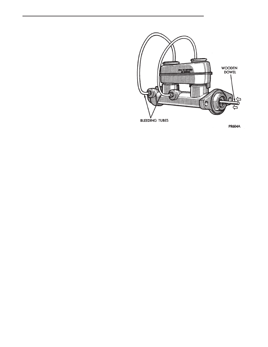
Clamp master cylinder in vise and attach Bleeding

Tubes, Special Tool C-4546 (Fig. 5).

Use a residual valve on outlet of each bleeder tube, to

keep air from being drawn back up tube and into
master cylinder.

Fill both reservoirs to the appropriate full mark, with

approved brake fluid.

Depress push rod slowly and then allow pistons to

return. Repeat several times until all air bubbles are
expelled (Fig. 5).

Remove bleeding tubes from master cylinder. Plug

outlet ports on master cylinder and install caps on fluid
reservoir.

Remove master cylinder from vise and install master

cylinder back on the power brake unit.

It is not necessary to bleed the entire hydraulic

system after replacing the master cylinder. Pro-
viding that the master cylinder had been thor-
oughly bled of all air and filled with approved
brake fluid before installing it on the vehicle.

INSTALL

Position master cylinder over studs on power brake

unit, align push rod with master cylinder piston.

Install master cylinder to power brake unit attaching

nuts (Fig. 4) and tighten to 28 N

Im (250 in. lbs.).

Connect brake tubes to master cylinder outlet ports.

Tighten the brake tube to master cylinder fittings to 17
N

Im (145 in. lbs.).

POWER BRAKES

INDEX

page

page

General Information

. . . . . . . . . . . . . . . . . . . . . . . 51

Service Procedures

. . . . . . . . . . . . . . . . . . . . . . . 52

GENERAL INFORMATION

A 270 mm power brake booster assembly is used on

these vehicles (Fig. 1 and 2).

The purpose of the power brake booster is to reduce

the amount of force applied to the brake pedal, to
obtain the required hydraulic pressure in the brake
system to stop the vehicle.

The power brake booster can be identified if required,

by the tag attached to the body of the booster assembly
(Fig. 1). This tag contains the following information.
The production part number of the power booster
assembly, the date it was built and who manufactured
it.

The power brake booster assembly is not a

repairable part and must be replaced as a com-
plete unit if it is found to be faulty in any way.
The power booster vacuum check valve is not
repairable but can be replaceable as an assembly.

The power brake booster in vacuum operated. The

vacuum is supplied from the intake manifold through
the power brake booster check valve (Fig. 1).

As the brake pedal is depressed, the power boosters

input rod moves forward. This opens and closes valves
in the power booster, creating a vacuum on one side of
a diaphragm and allowing atmospheric pressure to
enter on the other. This difference in pressure forces
the output rod of the power booster out against the
primary piston of the master cylinder. As the pistons in
the master cylinder move forward this creates the
hydraulic pressure in the brake system.

Different systems and engine combinations require

different vacuum hose routings. The hose is needed to
supply the power brake unit with a vacuum signal from
the engines intake manifold. This vacuum signal is
required for the proper operation of the power brake
unit. Below is listed the different hose routing require-
ments and routing illustrations.

Fig. 5 Bleeding Master

.

BRAKES

5 - 51

Vehicles equipped with the Chrysler 2.5L engine use

a charcoal filter in the hose between the booster and
the throttle body (Fig. 3).

Vehicles equipped with the optional 3.0L and 3.3L

engine use a preformed vacuum hose connected di-
rectly to the intake manifold (Fig. 4 and 5).

SERVICE PROCEDURES

POWER BRAKE BOOSTER ASSEMBLY

REMOVE

(1) Remove the 2 nuts (Fig. 6) attaching master

cylinder assembly to power brake unit.

(2) Carefully slide master cylinder off mounting

studs with brake lines attached, and allow the assem-
bly to rest against fender shield.

Fig. 1 Power Brake Booster Identification

Fig. 2 Power Brake Booster Assembly

Fig. 3 Power Brake Unit/Vacuum Hose Connections

2.5L TBI and 2.5L Turbocharged Engines

Fig. 4 Power Brake Unit/Vacuum Hose Connections

3.0L Engine

5 - 52

BRAKES

.

(3) Disconnect vacuum hose from power brake

booster check valve (Fig. 1). DO NOT REMOVE
CHECK

VALVE

FROM

POWER

BRAKE

BOOSTER.

(4) From under instrument panel, position a small

screwdriver between the center tang on the power
brake booster input rod to brake pedal pin retaining
clip.

(5) Rotate screwdriver enough to allow retainer clip

center tang to pass over end of brake pedal pin and pull
retainer clip off pin. Discard retainer clip it is not
to be reused, replace only with a new retainer
clip.

(6) Remove the four nuts that attach the power

brake booster to the vehicle dash panel. Nuts are
accessible from under the dash panel in the area of the
steering column and pedal bracket (Fig. 7).

(7) Unfasten brackets on steel heater water line at

dash panel and left frame rail. On Manual Transmis-
sion vehicles, 
unfasten clutch cable bracket at shock
tower and move aside.

(8) Slide the power brake unit up and to the left

(mounting holes are slotted) on the dash panel, then
tilt inboard and up to remove.

CAUTION: Do not attempt to disassemble power
brake unit as this booster is serviced ONLY as a
complete assembly.

INSTALL

(1) Position power brake booster onto dash panel.
(2) Install and tighten the 4 power brake booster to

dash panel mounting nuts (Fig. 7) to 29 N

Im (250 in.

lbs.) torque.

(3) Install steel heater water line and clutch cable

bracket, if so equipped.

Fig. 5 3.3L Engine Power Brake Unit/Vacuum Hose

Connections

Fig. 6 Master Cylinder Mounting

Fig. 7 Power Brake Booster Mounting

.

BRAKES

5 - 53

(4) Carefully position master cylinder on power

brake unit.

(5) Install and tighten the 2 master cylinder to

power booster mounting nuts (Fig. 6) to 29 N

Im (250

in. lbs.) torque.

(6) Connect vacuum hose onto the check valve, lo-

cated on the power brake unit.

(7) Using lubriplate, or equivalent, coat the bearing

surface of pedal pin (Fig. 7).

(8) Connect power brake booster input rod to brake

pedal pin and install a NEW retainer clip. Use only a
new retainer clip DO NOT USE the old clip.

(9) Check stop light operation.

WHEEL BEARINGS

FRONT WHEEL BEARINGS

Front wheel drive vehicles are equipped with perma-

nently sealed front wheel bearings. There is no periodic
lubrication or maintenance recommended for these
units. However if during servicing of the brake system,
service to the front wheel bearing is required refer to
Group 2, Suspension in this service manual.

REAR WHEEL BEARINGS (FRONT WHEEL DRIVE)

NORMAL SERVICE

The lubricant in the rear wheel bearings should be

inspected whenever the hubs are removed to inspect or
service the brake system, or every 30,000 miles (48 000
km). The bearing should be cleaned and repacked with
a High Temperature Multipurpose E.P. Grease when-
ever the brake drums are resurfaced.

INSPECTION

Check lubricant to see that it is adequate in quantity

and quality. If the grease is low in quantity, contains
dirt, appears dry or milky in appearance, the bearings
must be cleaned and repacked. Do not add grease to
a lubricated wheel bearing, it must be cleaned
and completely repacked. Mixing of different
types of greases in wheel bearings should be
avoided since it may result in excessive thinning
and leakage of the grease.

REMOVAL AND INSTALLATION

For the servicing, removal and installation of the

rear wheel bearings follow the procedure listed below.

(1) Remove the rear tire and wheel assembly.
(2) Remove grease cap, cotter pin, nut lock, nut,

thrust washer and outer wheel bearing.

(3) Carefully slide hub or drum from spindle. Do not

drag inner bearing or grease seal over stub axle
(thread, bearing, and oil seal may be damaged.)
Using an appropriate tool remove the grease seal and
inner bearing from the drum or hub. Discard grease
seal, a new seal should be used when reinstalling the
inner bearing. (See Fig. 1)

(5) Thoroughly clean all old grease from the outer

and inner bearings, bearing cups and hub cavity (See
Fig. 1). To clean bearings, soak them in an appro-
priate cleaning solvent. Strike the flat surface of
the bearing inner race against a hardwood block
several times, to loosen grease. Immerse the
bearings in solvent between blows to jar loose

and wash old particles of hardened grease from
bearings. Repeat this operation until bearings
are clean. Bearings can be dried using com-
pressed air but do not spin the bearings. After
cleaning, oil the bearings with engine oil. Insert
the bearing into its appropriate cup, apply pres-
sure to the bearing while rotating it to test them
for pitting and roughness. Replace all worn or
defective bearings. If bearing shows signs of
pitting or roughness they should be replaced.
Bearings must be replaced as a set, both the cup
and the bearing need to be replaced at the same
time. If bearings are suitable for further use,
remove engine oil from bearings using appropri-
ate solvent and dry bearings. Repack the bear-
ings using a Multi-Purpose NLGI. Grade 2 EP
Grease such as Mopar

or equivalent, and place

them in a clean covered container until ready for
installation. If a bearing packer is not available,
hand pack grease into all cavities between bear-
ing cage and rollers.

(6) If bearings and cups are to be replaced, remove

cups from the drum or hub using a brass drift or
suitable remover.

Fig. 1 Rear Wheel Bearings

5 - 54

BRAKES

.


Content   ..  165  166  167  168   ..