Chrysler Town & Country/Voyager, Dodge Caravan, Plymouth Voyager. Manual - part 23


  Index      Chrysler     Chrysler Town & Country/Voyager, Dodge Caravan, Plymouth Voyager - service repair manual 1992 year


Search            


Content   ..  21  22  23  24   ..


Chrysler Town & Country/Voyager, Dodge Caravan, Plymouth Voyager. Manual - part 23


RPM is above 2400 RPM (resulting in a 0 volt input to
the engine controller) a fault code will not be entered
into memory. This is because the condition does not
occur within the specified RPM range.

There are several operating conditions that the en-

gine controller does not monitor and set fault codes for.
Refer to Monitored Circuits and Non-Monitored Cir-
cuits in this section.

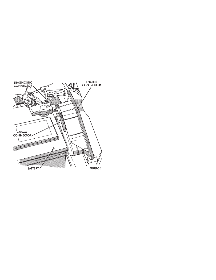
Stored fault codes can be displayed either by cycling

the ignition key On - Off - On - Off - On, or through use
of the Diagnostic Readout Box II (DRB II). The DRB II
connects to the diagnostic connector in the vehicle (Fig.
22).

MONITORED CIRCUITS

The engine controller can detect certain fault condi-

tions in the fuel injection system.

Open or Shorted Circuit - The engine controller

can determine if the sensor output (input to controller)
is within proper range. Also, the controller can deter-
mine if the circuit is open or shorted.

Output Device Current Flow - The engine control-

ler senses whether the output devices are hooked up. If
there is a problem with the circuit, the controller
senses whether the circuit is open, shorted to ground,
or shorted high.

Oxygen Sensor - The engine controller can deter-

mine if the oxygen sensor is switching between rich
and lean once the system has entered closed loop. Refer
to Modes of Operation in this section for an explanation
of closed loop operation.

NON-MONITORED CIRCUITS

The engine controller does not monitor the following

circuits, systems and conditions that could have mal-
functions that result in driveability problems. Fault
codes may not be displayed for these conditions. How-
ever, problems with these systems may cause fault
codes to be displayed for other systems. For example, a
fuel pressure problem will not register a fault directly,
but could cause a rich or lean condition. This could
cause an oxygen sensor fault to be stored in the engine
controller.

Fuel Pressure - Fuel pressure is controlled by the

fuel pressure regulator. The engine controller cannot
detect a clogged fuel pump inlet filter, clogged in-line
fuel filter, or a pinched fuel supply or return line.
However, these could result in a rich or lean condition
causing an oxygen sensor fault to be stored in the
engine controller.

Secondary Ignition Circuit - The engine control-

ler cannot detect an inoperative ignition coil, fouled or
worn spark plugs, ignition cross firing, or open spark
plug cables.

Engine Timing - The engine controller cannot de-

tect an incorrectly indexed timing chain, camshaft
sprocket and crankshaft sprocket. The engine control-
ler also cannot detect an incorrectly indexed distribu-
tor. However, these could result in a rich or lean
condition causing an oxygen sensor fault to be stored in
the engine controller.

Cylinder Compression - The engine controller

cannot detect uneven, low, or high engine cylinder
compression.

Exhaust System - The engine controller cannot

detect a plugged, restricted or leaking exhaust system.

Fuel Injector Malfunctions - The engine control-

ler cannot determine if the fuel injector is clogged, the
pintle is sticking or the wrong injector is installed.
However, these could result in a rich or lean condition
causing an oxygen sensor fault to be stored in the
engine controller.

Excessive Oil Consumption - Although the engine

controller monitors exhaust stream oxygen content
when the system is in closed loop, it cannot determine
excessive oil consumption.

Throttle Body Air Flow - The engine controller

cannot detect a clogged or restricted air cleaner inlet or
filter element.

Evaporative System - The engine controller will

not detect a restricted, plugged or loaded evaporative
purge canister.

Vacuum Assist - Leaks or restrictions in the

vacuum circuits of vacuum assisted engine control
system devices are not monitored by the engine con-
troller. However, these could result in a MAP sensor
fault being stored in the engine controller.

Fig. 22 Diagnostic Connector Location

.

FUEL SYSTEM

14 - 39

Engine Controller System Ground - The engine

controller cannot determine a poor system ground.
However, a fault code may be generated as a result of
this condition.

Engine Controller Connector Engagement - The

engine controller cannot determine spread or damaged
connector pins. However, a fault code may be generated
as a result of this condition.

HIGH AND LOW LIMITS

The engine controller compares input signal voltages from

each input device with established high and low limits that
are programmed into it for that device. If the input voltage is
not within specifications and other fault code criteria are
met, a fault code will be stored in memory. (Other fault code
criteria might include engine RPM limits or input voltages
from other sensors or switches that must be present before a
fault condition can be verified).

FAULT CODE DESCRIPTION

When a fault code appears, it indicates that the

Engine Controller has recognized an abnormal condi-
tion in the system. Fault codes can be obtained from
the Check Engine lamp on the Instrument Panel or
from the Diagnostic Readout Box II (DRB II). Fault
codes indicate the results of a failure but do not
identify the failed component directly.

SYSTEMS TEST

Be sure to apply parking brake and/or block

wheels before performing idle check or adjust-
ment, or any engine running tests.

OBTAINING FAULT CODES

(1) ]Connect DRBII to the diagnostic connector located in

the engine compartment near the engine controller.

(2) Start the engine if possible, cycle the transmission

selector and the A/C switch if applicable. Shut off the engine.

(3) Turn the ignition switch on, access Read Fault

Screen. Record all the fault messages shown on the
DRB II. Observe the check engine lamp on the instru-
ment panel. The lamp should light for 3 seconds then
go out (bulb check).

STATE DISPLAY TEST MODE

The switch inputs used by the engine controller have

only two recognized states, HIGH and LOW. For this
reason, the engine controller cannot recognize the
difference between a selected switch position versus an
open circuit, a short circuit, or a defective switch. If the
change is displayed, it can be assumed that the entire
switch circuit to the engine controller is functional.
From the state display screen access either State
Display Inputs and Outputs or State Display Sensors.

STATE DISPLAY INPUTS AND OUTPUTS

Connect the DRB II tester to the vehicle and access the

State Display screen. Then access Inputs and Outputs. The

following is a list of the engine control system functions
accessible through the Inputs and Outputs screen:

Park/Neutral Switch (automatic transmission only)
Speed Control Resume
Brake Switch
Speed Control On/Off
Speed Control Set
A/C Switch Sense
Z2 Voltage Sense
B1 Voltage Sense
S/C (Speed Control) Vent Solenoid
S/C (Speed Control) Vacuum Solenoid
PTU Solenoid
A/C Clutch Relay
EMR Lamp
Auto Shutdown Relay
Radiator Fan Relay
Purge Solenoid
Check Engine Lamp

STATE DISPLAY SENSORS

Connect the DRB II tester to the vehicle and access the

State Display screen. Then access Sensor Display. The fol-
lowing is a list of the engine control system functions acces-
sible through the Sensor Display screen:

Battery Temp Sensor
Oxygen Sensor Signal
Coolant Temperature
Coolant Temp Sensor
Throttle Position
Minimum Throttle
Battery Voltage
MAP Sensor Reading
AIS Motor Position
Added Adaptive Fuel
Adaptive Fuel Factor
Barometric Pressure
Min Airflow Idl Spd
Engine Speed
Fault #1 Key-On Info
Module Spark Advance
Speed Control Target
Fault #2 Key-On Info
Fault #3 Key-On Info
Speed Control Status
Speed Control Switch Voltage
Charging System Goal
Theft Alarm Status
Map Sensor Voltage
Vehicle Speed
Oxygen Sensor State
MAP Gauge Reading
Throttle Opening
Total Spark Advance

14 - 40

FUEL SYSTEM

.

FAULT CODE DESCRIPTION

.

FUEL SYSTEM

14 - 41

CIRCUIT ACTUATION TEST MODE

The circuit actuation test mode checks for proper

operation of output circuits or devices which the engine
controller cannot internally recognize. The engine con-
troller can attempt to activate these outputs and allow
an observer to verify proper operation. Most of the tests
provide an audible or visual indication of device opera-
tion (click of relay contacts, spray fuel, etc.). Except for
intermittent conditions, if a device functions properly

during testing, assume the device, its associated wir-
ing, and driver circuit working correctly.

OBTAINING CIRCUIT ACTUATION TEST

Connect the DRB II tester to the vehicle and access

the Actuators screen. The following is a list of the
engine control system functions accessible through
Actuators screens:

FAULT CODE DESCRIPTION (CON’T)

14 - 42

FUEL SYSTEM

.


Content   ..  21  22  23  24   ..