Chrysler Town & Country/Voyager, Dodge Caravan, Plymouth Voyager. Manual - part 22


  Index      Chrysler     Chrysler Town & Country/Voyager, Dodge Caravan, Plymouth Voyager - service repair manual 1992 year


Search            


Content   ..  20  21  22  23   ..


Chrysler Town & Country/Voyager, Dodge Caravan, Plymouth Voyager. Manual - part 22


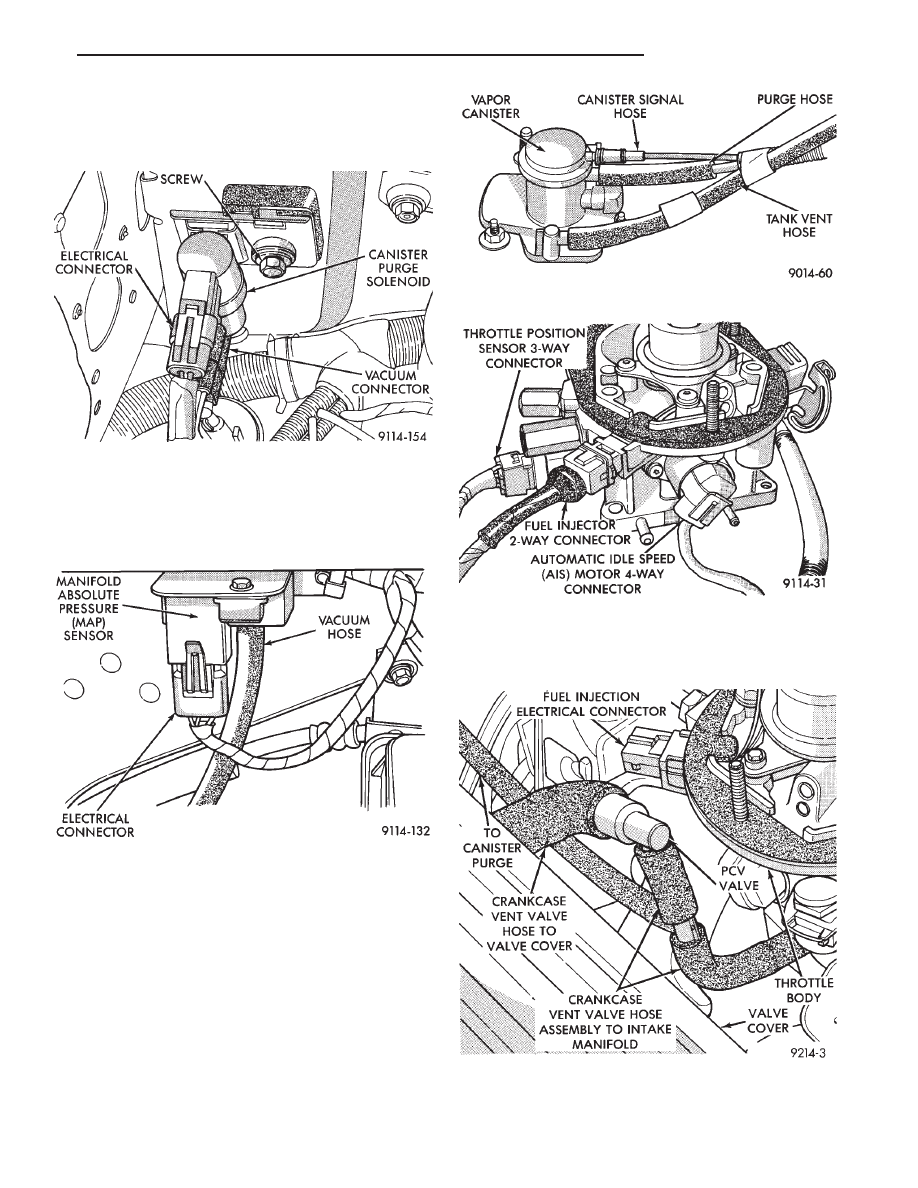
(2) Verify that the electrical connector is attached to

the Canister Purge Solenoid (Fig. 3).

(3) Verify that vacuum connection at Canister Purge

Solenoid is secure and not leaking.

(4) Verify the harness connector is attached to the

MAP sensor (Fig. 4).

(5) Verify manifold absolute pressure sensor vacuum

hose is attached at MAP sensor (Fig. 4).

(6) Verify that alternator wiring and belt are cor-

rectly installed and tightened.

(7) Verify that hoses are securely attached to vapor

canister (Fig. 5).

(8) Verify that the throttle body wiring harness is

connected to main harness.

(9) Verify the harness connector is attached to AIS

motor (Fig. 6).

(10) Verify the harness connector is attached to the

throttle position sensor (Fig. 6).

(11) Verify the harness connector is attached to the

fuel injector (Fig. 6).

(12) Verify the hose from PCV valve is securely

attached to the intake manifold vacuum port (Fig. 7).

Fig. 3 Canister Purge Solenoid

Fig. 4 Manifold Absolute Pressure (MAP) Sensor

Location

Fig. 5 Vapor Canister

Fig. 6 Throttle Body Wiring Connections

Fig. 7 Vacuum Hose from Intake Manifold to PCV

Valve

.

FUEL SYSTEM

14 - 35

(13) Verify the vacuum connections on the front and

rear of throttle body are secure and not leaking (Figs.
8, and 9).

(14) Verify the heated air door vacuum connection is

connected and not leaking.

(15) Verify power brake and speed control vacuum

connectors are tight (Fig. 10).

(16) Verify all ignition cables are in correct order and

seated into place (Fig. 11).

(17) Verify electrical connector is attached to coolant

temperature sensor (Fig. 12).

(18) Verify

battery

negative

ground

eyelet

is

mounted to the cylinder head (left side) (Fig. 12).

(19) Verify the harness connector is attached to

distributor (Fig. 13).

(20) Verify radiator fan electrical connection is se-

cure.

(21) Verify oil pressure switch electrical connections

are secure (Fig. 13).

(22) On vehicles with an automatic transmission,

ensure the neutral safety switch electrical connector is
secure (Fig. 14).

Fig. 8 Throttle Body Vacuum Ports—Front

Fig. 9 Throttle Body Vacuum Ports—Rear

Fig. 10 Power Brake and Speed Control Vacuum

Connection

Fig. 11 Ignition Cable Routing and Connection

Fig. 12 Coolant Temperature Sensor

14 - 36

FUEL SYSTEM

.

G(23) On vehicles with an automatic transmission,

check torque convertor lockup solenoid electrical con-
nection (Fig. 14).

(24) Check the 60-way electrical connection at the

engine controller for damage or spread terminals.
Verify that the 60-way connector is fully inserted into
the socket on the Engine Controller (Fig. 15). Ensure
that wires are not stretched or pulled out of the
connector.

(25) Verify all electrical connectors are fully inserted

into relays (Fig. 16 and Fig. 17).

(26) Ensure battery connections are clean and tight.
(27) Verify engine harness to main harness connec-

tions are fully inserted.

Fig. 13 Distributor, Oil Pressure Switch, and Radia-

tor Fan Electrical Connections

Fig. 14 Automatic Transmission Electrical Connec-

tions

Fig. 15 Engine Controller Electrical Connector

Fig. 16 ASD, Fuel Pump, Radiator Fan and Starter

Relays

.

FUEL SYSTEM

14 - 37

(28) Check distance sensor connector (Fig. 18).

(29) Verify engine ground strap is attached at the

engine and dash panel (Figs. 19 and 20).

(30) Verify the harness connector is attached to the

heated oxygen sensor (Fig. 21).

(31) Check Hose and Wiring Connections at Fuel

Pump. Check that wiring connector is making contact
with terminals on pump.

ON BOARD DIAGNOSTICS

The engine controller has been programmed to moni-

tor many different circuits of the fuel injection system.
If a problem is sensed with a monitored circuit often
enough to indicate an actual problem, the controller
stores a fault. If the problem is repaired or ceases to
exist, the engine controller cancels the Fault Code after
51 vehicle key on/off cycles.

Certain criteria must be met for a fault code to be

entered into engine controller memory. The criteria
may be a specific range of engine RPM, engine tem-
perature, and/or input voltage to the engine controller.

It is possible that a fault code for a monitored circuit

may not be entered into memory even though a mal-
function has occurred. This may happen because one of
the fault code criteria for the circuit has not been met.
For example, assume that one of the fault code
criteria for the MAP sensor circuit is that the engine
must be operating between 750 and 2000 RPM to be
monitored for a fault code. If the MAP sensor output
circuit shorts to ground when engine

Fig. 17 A/C Clutch and A/C Fan Relays

Fig. 18 Distance Sensor Wiring Connection

Fig. 19 Engine Ground Strap at Intake Manifold

Fig. 20 Engine Ground Strap to Dash Panel

Fig. 21 Heated Oxygen Sensor Electrical Connec-

tion

14 - 38

FUEL SYSTEM

.


Content   ..  20  21  22  23   ..