Chrysler Town & Country/Voyager, Dodge Caravan, Plymouth Voyager. Manual - part 21
CRUISE OR IDLE MODE
When the engine is at operating temperature this is
a CLOSED LOOP mode. During cruising speed and at
idle the following inputs are received by the engine
controller:
• coolant temperature
• manifold absolute pressure
• engine speed
• throttle position
• exhaust gas oxygen content
• A/C control positions
• battery voltage
The engine controller provides a ground path for the
injector to precisely control injector pulse width. The
controller energizes the injector twice per engine revo-
lution. The engine controller controls engine idle speed
and ignition timing. The engine controller controls the
air/fuel ratio according to the oxygen content in the
exhaust gas.
ACCELERATION MODE
This is a CLOSED LOOP mode. The engine control-
ler recognizes an abrupt increase in throttle position or
MAP pressure as a demand for increased engine output
and vehicle acceleration. The engine controller in-
creases injector pulse width in response to increased
fuel demand.
DECELERATION MODE
This is a CLOSED LOOP mode. During deceleration
the following inputs are received by the engine control-
ler:
• coolant temperature
• manifold absolute pressure
• engine speed
• throttle position
• exhaust gas oxygen content
• A/C control positions
• battery voltage
The engine controller may receive a closed throttle
input from the throttle position sensor (TPS) when it
senses an abrupt decrease in manifold pressure. This
indicates a hard deceleration. The engine controller
may reduce injector firing to once per engine revolu-
tion. This helps maintain better control of the air-fuel
mixture (as sensed through the O
2
sensor).
During a deceleration condition, the engine control-
ler grounds the exhaust gas recirculation (EGR) and
evaporative purge solenoids. When these solenoids are
grounded, the EGR and canister purge functions stop.
WIDE OPEN THROTTLE MODE
This is an OPEN LOOP mode. During wide-open-
throttle operation, the following inputs are received by
the engine controller:
• coolant temperature
• manifold absolute pressure
• engine speed
• throttle position
When the engine controller senses a wide open
throttle condition through the throttle position sensor
(TPS) it will:
• De-energize the air conditioning relay. This disables
the air conditioning system.
The exhaust gas oxygen content input is not accepted
by the engine controller during wide open throttle
operation. The engine controller will adjust injector
pulse width to supply a predetermined amount of
additional fuel.
IGNITION SWITCH OFF MODE
When the ignition switch is turned to the OFF
position, the following occurs:
• All outputs are turned off.
• No inputs are monitored.
• The engine controller shuts down.
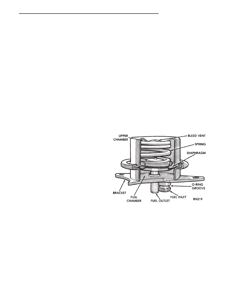
FUEL PRESSURE REGULATOR
The pressure regulator is a mechanical device lo-
cated at the top of the throttle body (Fig. 16). Its
function is to maintain a constant 270 kPa (39 PSI)
across the fuel injector tip.
The regulator uses a spring loaded rubber dia-
phragm to uncover a fuel return port. When the fuel
pump operates, fuel flows past the injector into the
regulator. The blocked return port restricts fuel from
flowing any further. When fuel pressure reaches 270
kPa (39 PSI) it pushes on the diaphragm, compressing
the spring, and uncovers the fuel return port. The
diaphragm and spring will constantly move from an
open to closed position to keep the fuel pressure con-
stant.
Fig. 16 Fuel Pressure Regulator
.
FUEL SYSTEM
14 - 31