Chrysler Town & Country/Voyager, Dodge Caravan, Plymouth Voyager. Manual - part 20


  Index      Chrysler     Chrysler Town & Country/Voyager, Dodge Caravan, Plymouth Voyager - service repair manual 1992 year


Search            


Content   ..  18  19  20  21   ..


Chrysler Town & Country/Voyager, Dodge Caravan, Plymouth Voyager. Manual - part 20


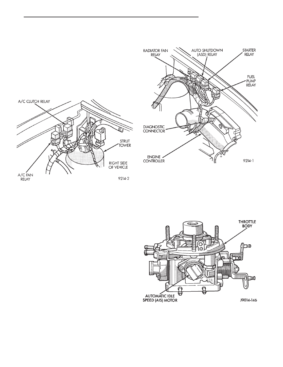
ergizes. The A/C fan relay energizes when the air
conditioning or defrost switch is put in the ON position
and the low pressure, A/C cycling, and high pressure
switches close.

With the engine operating, the engine controller

cycles the air conditioning clutch on and off when the
A/C switch closes with the blower motor switch in the
on position. When the engine controller senses low idle
speeds or wide open throttle through the throttle
position sensor, it de-energizes the A/C clutch relay.
The relay contacts open, preventing air conditioning
clutch engagement.

ALTERNATOR FIELD—ENGINE CONTROLLER OUT-
PUT

The engine controller regulates the charging system

voltage within a range of 12.9 to 15.0 volts. Refer to
Group 8A for charging system information.

AUTO SHUTDOWN (ASD) RELAY AND FUEL PUMP
RELAY—ENGINE CONTROLLER OUTPUT

The engine controller operates the auto shutdown

(ASD) relay and fuel pump relay through one ground
path. The controller operates the relays by switching
the ground path on and off. Both relays turn on and off
at the same time.

The ASD relay connects battery voltage to the fuel

injector and ignition coil. The fuel pump relay connects
battery voltage to the fuel pump and oxygen sensor
heating element.

The engine controller turns the ground path off when

the ignition switch is in the Off position. Both relays
are off. When the ignition switch is in the On or Crank
position, the engine controller monitors the distributor
pick-up signal to determine engine speed and ignition
timing (coil dwell). If the engine controller does not
receive a distributor signal when the ignition switch is
in the Run position, it will de-energize both relays.
When the relays are de-energized, battery voltage is
not supplied to the fuel injector, ignition coil, fuel pump
and oxygen sensor heating element.

The ASD relay and fuel pump relay are mounted on

the drivers side fender well, near to the engine control-
ler (Fig. 11).

AUTOMATIC IDLE SPEED (AIS) MOTOR—ENGINE
CONTROLLER OUTPUT

The idle speed stepper motor is mounted on the

throttle body and is controlled by the engine controller
(Fig. 12). The engine controller adjusts engine idle
speed through the AIS to compensate for engine load or
ambient conditions.

The throttle body has an air bypass passage that

provides air for the engine at idle (the throttle blade

Fig. 10 Relay Identification

Fig. 11 Auto Shutdown Relay

Fig. 12 Automatic Idle Speed Motor

.

FUEL SYSTEM

14 - 27

is closed). The AIS motor pintle protrudes into the
air bypass passage and regulates air flow through it.

The engine controller adjusts engine idle speed by

moving the AIS motor pintle in and out of the bypass
passage. The adjustments are based on inputs the
controller receives. The inputs are from the throttle
position sensor, speed sensor (distributor pick-up
coil), coolant temperature sensor, and various switch
operations (brake, park/neutral, air conditioning).
Deceleration die out is also prevented by increasing
airflow when the throttle is closed quickly after a
driving (speed) condition.

CANISTER PURGE SOLENOID—ENGINE
CONTROLLER OUTPUT

Vacuum for the Evaporative Canister is controlled

by the Canister Purge Solenoid (Fig. 13). The sole-
noid is controlled by the engine controller.

The engine controller operates the solenoid by

switching the ground circuit on and off based on en-
gine operating conditions. When energized, the sole-
noid prevents vacuum from reaching the evaporative
canister. When not energized the solenoid allows vac-
uum to flow to the canister.

During warm-up and for a specified time period af-

ter hot starts the engine controller grounds the purge
solenoid causing it to energize. Vacuum does not op-
erate the evaporative canister valve.

The engine controller removes the ground to the

solenoid when the engine reaches a specified temper-
ature and the time delay interval has occurred.
When the solenoid is de-energized, vacuum flows to
the canister purge valve. Vapors are purged from the
canister and flow to the throttle body.

The purge solenoid is also energized during certain

idle conditions to update the fuel delivery calibra-
tion.

CHECK ENGINE LAMP—ENGINE CONTROLLER
OUTPUT

The engine controller supplies a check engine lamp

on/off signal to the instrument panel through the
CCD Bus. The CCD Bus is a communications port.
Various modules use the CCD Bus to exchange infor-
mation.

The Check Engine Lamp comes on each time the

ignition key is turned ON and stays on for 3 seconds
as a bulb test. The Check Engine Lamp warns the
operator that the engine controller has entered a
Limp-in mode. During Limp-in-Mode, the controller
attempts to keep the system operational. The check
engine lamp signals the need for immediate service.
In limp-in mode, the Engine controller compensates
for the failure of certain components that send incor-
rect signals. The controller substitutes for the incor-
rect signals with inputs from other sensors.

Signals that can trigger the Check Engine

Lamp.
• Coolant Temperature Sensor

• Manifold Absolute Pressure Sensor

• Throttle Position Sensor

• Battery Voltage Input

• An Emissions Related System

• Charging system

The Check Engine Lamp can also be used to dis-

play fault codes. Cycle the ignition switch on, off, on,
off, on, within five seconds and any fault codes stored
in the Engine controller will be displayed. Refer to
On

Board

Diagnostics

in

the

General

Diagnosis—2.5L TBI Engines section of this Group
for Fault Code Descriptions.

DIAGNOSTIC CONNECTOR—ENGINE CONTROLLER
OUTPUT

The diagnostic connector provides the technician

with the means to connect the DRB II tester to diag-
nosis the vehicle.

EMISSION MAINTENANCE REMINDER (EMR)
LAMP—ENGINE CONTROLLER OUTPUT

The

Emissions

Maintenance

Reminder

System

(EMR) is incorporated into the engine controller. The
engine controller records the vehicle mileage and
stores it into memory every 8 miles. At that time,
the engine controller checks for the 60,000, 82,500,
and 120,000 mileage trip points. When the current
mileage matches one of the above mentioned trip
points, the EMR lamp on the instrument panel is ac-
tivated.

Certain components must be replaced at the indi-

cated mileage, or when the EMR lamp stays on with
the key in the on position, whichever occurs first. Af-
ter performing the required maintenance, the EMR
lamp must be reset to turn the lamp off.

For more information, refer to Group 25 or the ap-

propriate diagnostic manual.

Fig. 13 Canister Purge Solenoid

14 - 28

FUEL SYSTEM

.

FUEL INJECTOR—ENGINE CONTROLLER OUTPUT

The Fuel Injector is an electric solenoid driven by the

engine controller (Fig 14).

Based on sensor inputs, the engine controller deter-

mines when and how long the fuel injector should
operate.

The amount of time the injector operates is referred

to as injector pulse width. The auto shutdown (ASD)
relay supplies battery voltage to the injector. The
engine controller supplies the ground path. By switch-
ing the ground path on and off, the engine controller
adjusts injector pulse width. When the controller sup-
plies a ground path, a spring loaded needle or arma-
ture lifts from its seat. Fuel flows through the orifice
and deflects off the sharp edge of the injector nozzle.
The resulting fuel sprays forms a 45° cone shaped
pattern before entering the air stream in the throttle
body.

Fuel is supplied to the injector constantly at regu-

lated 270 Kpa (39 psi). Unused fuel returns to the fuel
tank.

IGNITION COIL—ENGINE CONTROLLER OUTPUT

The engine controller provides a ground contact

(circuit) for energizing the ignition coil. When the
controller breaks the contact, the energy in the coil
primary transfers to the secondary causing the spark.
The auto shutdown (ASD) relay provides battery volt-
age to the ignition coil positive terminal. The engine
controller will de-energize the ASD relay if it does not
receive an input from the distributor pick-up. Refer to
Auto

Shutdown

(ASD)

Relay/Fuel

Pump

Relay—Engine Controller Output in this section for
relay operation.

The ignition coil is mounted on the hot box next to

the thermostat housing (Fig. 15).

PART THROTTLE UNLOCK SOLENOID—ENGINE
CONTROLLER OUTPUT

Three-speed automatic transaxles use a part throttle

unlock solenoid. The engine controller controls the
lock-up of the torque convertor through the part
throttle unlock solenoid. The transmission is locked up
only in direct drive mode. Refer to Group 21 for
transmission information.

RADIATOR FAN RELAY—ENGINE CONTROLLER
OUTPUT

The radiator fan is energized by the engine controller

through the radiator fan relay. The radiator fan relay is
located on the drivers side fender well near to the
engine controller (Fig. 11). The engine controller
grounds the radiator fan relay when engine coolant
reaches a predetermined temperature. For more infor-
mation, refer to Group 7, Cooling Systems.

SPEED CONTROL SOLENOIDS—ENGINE CONTROL-
LER OUTPUT

The speed control vacuum and vent solenoids are

operated by the engine controller. When the engine
controller supplies a ground to the vacuum solenoid,
the speed control system opens the throttle plate.
When the controller supplies a ground to the vent
solenoid, the throttle blade closes. The engine control-
ler balances the two solenoids to maintain the set
speed. Refer to Group 8H for speed control information.

TACHOMETER—ENGINE CONTROLLER OUTPUT

The engine controller supplies engine RPM to the

instrument panel tachometer through the CCD Bus.

Fig. 14 Fuel Injector

Fig. 15 Ignition Coil

.

FUEL SYSTEM

14 - 29

The CCD Bus is a communications port. Various mod-
ules use the CCD Bus to exchange information. Refer
to Group 8E for more information.

MODES OF OPERATION

As input signals to the engine controller change, the

engine controller adjusts its response to the output
devices. For example, the engine controller must cal-
culate a different injector pulse width and ignition
timing for idle than it does for wide open throttle
(WOT). There are several different modes of operation
that determine how the engine controller responds to
the various input signals.

There are two different areas of operation, OPEN

LOOP and CLOSED LOOP.

During OPEN LOOP modes, the engine controller

receives input signals and responds according to preset
engine controller programming. Input from the oxygen
(O

2

) sensor is not monitored during OPEN LOOP

modes.

During CLOSED LOOP modes, the engine controller

does monitor the oxygen (O

2

) sensor input. This input

indicates to the engine controller whether or not the
calculated injector pulse width results in the ideal
air-fuel ratio of 14.7 parts air to 1 part fuel. By
monitoring the exhaust oxygen content through the O

2

sensor, the engine controller can fine tune the injector
pulse width. Fine tuning injector pulse width allows
the controller to achieve optimum fuel economy com-
bined with low emissions.

The single point fuel injection system has the follow-

ing modes of operation:
• Ignition switch ON - Zero RPM

• Engine start-up

• Engine warm-up

• Cruise (Idle)

• Acceleration

• Deceleration

• Wide Open Throttle

• Ignition switch OFF

The engine start-up (crank), engine warm-up, and

wide open throttle modes are OPEN LOOP modes.
Under most operating conditions, the acceleration,
deceleration, and cruise modes, with the engine at
operating temperature
, are CLOSED LOOP modes.

IGNITION SWITCH ON (ZERO RPM) MODE

When the single point fuel injection system is acti-

vated by the ignition switch, the following actions
occur:
• The engine controller determines atmospheric air
pressure from the MAP sensor input to determine basic
fuel strategy.
• The engine controller monitors the coolant tempera-
ture sensor and throttle position sensor inputs. The
engine controller modifies fuel strategy based on these
inputs.

When the key is in the ON position and the engine is

not running or cranking (zero rpm), the auto shutdown
(ASD) relay and fuel pump relay are not energized.
Therefore battery voltage is not supplied to the fuel
pump, ignition coil, fuel injector or oxygen sensor
heating element.

ENGINE START-UP MODE

This is an OPEN LOOP mode. The following actions

occur when the starter motor is engaged.

If the engine controller receives a distributor signal,

it energizes the auto shutdown (ASD) relay and fuel
pump relay. These relays supply battery voltage to the
fuel pump, fuel injector, ignition coil and oxygen sensor
heating element. If the engine controller does not
receive a distributor input, the ASD and fuel pump
relays will be de-energized after approximately one
second.

When the engine is idling within

664 RPM of the

target RPM, the controller compares current MAP
value with the atmospheric pressure value received
during the Ignition Switch On (Zero RPM) Mode. If a
minimum difference between the two is not detected, a
MAP sensor fault is set into memory.

Once the ASD relay and fuel pump relay have ener-

gized, the engine controller:
• Supplies a ground path to the injector. The injector
is pulsed four times per engine revolution instead of
the normal two pulses per revolution.
• Determines injector pulse width based on coolant
temperature, MAP sensor input, throttle position, and
the number of engine revolutions since cranking was
initiated.
• Monitors the coolant temperature sensor, distribu-
tor pick-up, MAP sensor, and throttle position sensor to
determine correct ignition timing.

ENGINE WARM-UP MODE

This is a OPEN LOOP mode. The following inputs

are received by the engine controller:
• coolant temperature

• manifold absolute pressure (MAP)

• engine speed (distributor pick-up)

• throttle position

• A/C switch

• battery voltage

The engine controller provides a ground path for the

injector to precisely control injector pulse width (by
switching the ground on and off). The controller ener-
gizes the injector twice per engine revolution. The
engine controller regulates engine idle speed (by ad-
justing the automatic idle speed motor) and ignition
timing.

14 - 30

FUEL SYSTEM

.


Content   ..  18  19  20  21   ..