Chrysler Town & Country/Voyager, Dodge Caravan, Plymouth Voyager. Manual - part 9


  Index      Chrysler     Chrysler Town & Country/Voyager, Dodge Caravan, Plymouth Voyager - service repair manual 1992 year


Search            


Content   ..  7  8  9  10   ..


Chrysler Town & Country/Voyager, Dodge Caravan, Plymouth Voyager. Manual - part 9


(15) Connect and coolant temperature sensor electri-

cal connector to sensor (Fig. 7).

(16) Connect PCV and brake booster supply hose to

intake plenum.

(17) Connect automatic idle speed (AIS) motor and

throttle position sensor (TPS) electrical connectors
(Fig. 5).

(18) Connect vacuum vapor harness to throttle body

(Fig. 5).

(19) Install throttle cable and transaxle kickdown

linkage (Fig. 4).

(20) Install air inlet hose assembly (Fig. 3).
(21) Install radiator to thermostat housing hose and

heater hose to heater pipe nipple.

(22) Fill cooling system, see Refilling System in

Cooling, Group 7.

(23) Connect negative battery cable.
(24) With the DRB II use ASD Fuel System Test to

pressurize system to check for leaks.

CAUTION: When using the ASD Fuel System Test,
The Auto Shutdown (ASD) Relay will remain ener-
gized for 7 minutes or until the ignition switch is
turned to the OFF position, or Stop All Test is se-
lected.

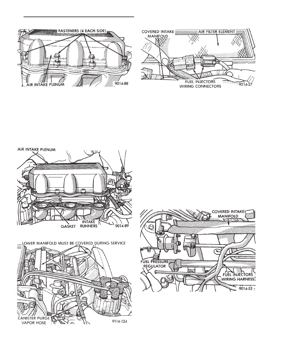
Fig. 8 Air Intake Plenum to Intake Manifold Attach-

ing Bolts

Fig. 9 Removing Air Intake Plenum

Fig. 10 Vacuum Connections for Fuel Rail and Fuel

Pressure Regulator

Fig. 11 Fuel Injector Wiring Harness

Fig. 12 Fuel Pressure Regulator to Fuel Rail Assem-

bly

.

EXHAUST SYSTEM AND INTAKE MANIFOLD

11 - 9

Fig. 13 Check Intake (Cross) Manifold Mounting

Surface

Fig. 14 Check Intake Plenum Mounting Surfaces

Fig. 15 Intake Plenum and Cylinder Head Mounting

Surface Specifications

Fig. 16 Nut Tightening Sequence for Intake (Cross)

Manifold

Fig. 17 Intake Plenum Tightening Sequence

11 - 10

EXHAUST SYSTEM AND INTAKE MANIFOLD

.

EXHAUST MANIFOLDS

REMOVAL

(1) Raise vehicle and disconnect exhaust pipe from

rear (cowl side) exhaust manifold at articulated joint.

(2) Disconnect Oxygen Sensor lead wire at the rear

exhaust manifold (Fig. 18).

(3) Remove bolts attaching cross-over pipe to mani-

fold (Figs. 2 and 19).

(4) Remove nuts attaching rear manifold to cylinder

head and remove manifold.

(5) Lower vehicle and remove screws attaching front

heat shield to front manifold (Fig. 2).

(6) Remove bolts fastening crossover pipe to front

exhaust manifold and nuts fastening manifold to cyl-
inder head. Remove assemblies.

INSPECTION

Inspect exhaust manifolds for damage or cracks and

check distortion of the cylinder head mounting surface

and exhaust crossover mounting surface with a
straightedge and thickness gauge (Fig. 20).

INSTALLATION

Install the gaskets with the numbers 1-3-5 embossed

on the top on the rear bank and those with numbers
2-4-6 on the front (Radiator side) bank (Fig. 21).

(1) Install rear exhaust manifold and tighten attach-

ing nuts to 20 N

Im (175 in. lbs.).

(2) Attach exhaust pipe to exhaust manifold and

tighten shoulder bolt to 28 N

Im (250 in. lbs.).

(3) Attach crossover pipe to exhaust manifold and

tighten bolt to 69 N

Im (51 ft. lbs.).

(4) Connect heated oxygen sensor lead (Fig. 18).
(5) Install front exhaust manifold and attach ex-

haust crossover.

(6) Install front manifold heat shield and tighten

attaching screws to 15 N

Im (130 in. lbs.) (Fig. 2).

Fig. 18 Separate Articulated Joint, Disconnect Oxy-

gen Sensor Wire

Fig. 19 Crossover Pipe

Fig. 20 Check Exhaust Manifold Mounting Surface

Fig. 21 Identify Exhaust Manifold Gaskets

.

EXHAUST SYSTEM AND INTAKE MANIFOLD

11 - 11

INTAKE/EXHAUST MANIFOLD 3.3L ENGINE

REMOVAL

(1) Perform fuel system pressure release procedure

(before attempting any repairs).

(2) Disconnect negative battery cable. Drain cooling

system. See Cooling System, Group 7.

FUEL SYSTEM PRESSURE RELEASE PROCE-
DURE

The MPI fuel system is under a constant pres-

sure of approximately 330 kPa (48 psi). Before
servicing the fuel pump, fuel lines, fuel filter,
throttle body or fuel injector, the fuel system
pressure must be released.

(a) Loosen fuel filler cap to release fuel tank pres-

sure.

(b) Disconnect injector wiring harness from engine

harness.

(c) Connect a jumper wire to ground terminal

Number 1 of the injector harness (Fig. 1) to engine
ground.

(d) Connect a jumper wire to the positive terminal

Number 2 of the injector harness (Fig. 1) and touch
the battery positive post for no longer than 5 seconds.
This releases system pressure.

(e) Remove jumper wires.
(f) Continue fuel system service.

(3) Remove air cleaner to throttle body hose assem-

bly (Fig. 2).

(4) Remove throttle cable (Fig. 3). Remove wiring

harness from throttle cable bracket.

(5) Remove automatic idle speed (AIS) motor and

throttle position sensor (TPS) wiring connectors from
throttle body (Fig. 4).

(6) Remove vacuum hose harness from throttle body

(Fig. 4).

(7) Remove PCV and brake booster hoses from air

intake plenum (Fig. 5).

(8) Remove EGR tube flange from intake plenum

(Fig. 5).

(9) Disconnect Charge Temperature Sensor electri-

cal connector. Remove vacuum harness connectors
from Intake Plenum (Fig. 5).

(10) Remove cylinder head to intake plenum strut

(Fig. 5).

(11) Disconnect MAP Sensor and heated Oxygen

Sensor electrical connection. Remove the engine
mounted ground strap (Fig. 6).

Fig. 1 Injector Harness Connector

Fig. 2 Throttle Body Assembly 3.3L

Fig. 3 Throttle Cable Attachment

11 - 12

EXHAUST SYSTEM AND INTAKE MANIFOLD

.


Content   ..  7  8  9  10   ..