Chrysler Town & Country/Voyager, Dodge Caravan, Plymouth Voyager. Manual - part 7
EXHAUST SYSTEM AND INTAKE MANIFOLD
CONTENTS
page
page
GENERAL INFORMATION
. . . . . . . . . . . . . . . . . . 1
SERVICE PROCEDURES
. . . . . . . . . . . . . . . . . . . 4
TORQUE SPECIFICATION
. . . . . . . . . . . . . . . . . 17
GENERAL INFORMATION
Throughout this group, references may be made to a
particular vehicle by letter or number designation. A
chart showing the breakdown of these designations is
included in the Introduction Section at the front of this
service manual.
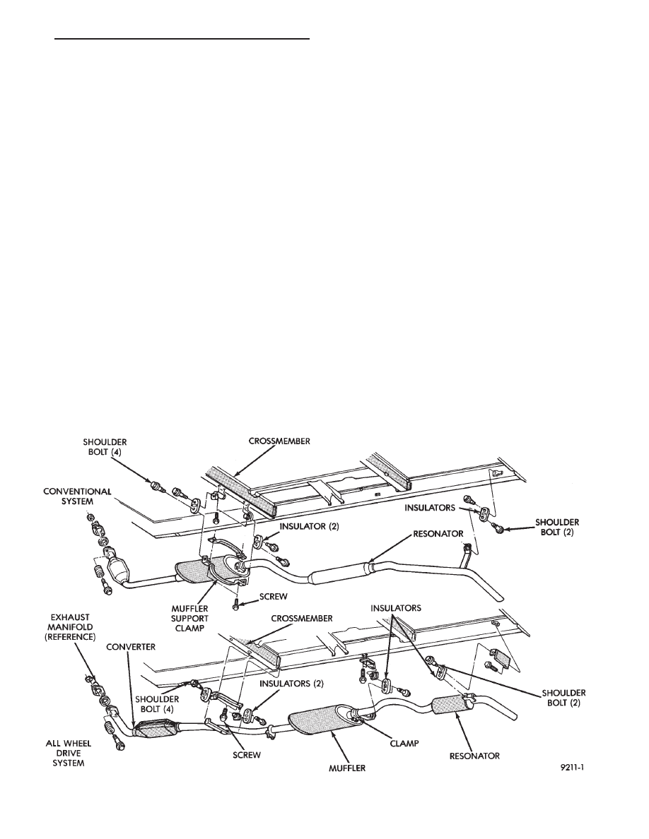
EXHAUST SYSTEMS
The exhaust systems are produced in several con-
figurations, depending on engine and vehicle (Fig. 1).
All wheel drive vehicles have underfloor catalytic con-
verters, front wheel drive vehicles require front
mounted catalytic converters. Tail pipes, mufflers, and
resonators
are
sized
and
tuned
to
each
vehicle/powertrain combination (Fig. 1).
CATALYTIC CONVERTERS
There is no regularly scheduled maintenance on any
Chrysler catalytic converter. If damaged, the converter
must be replaced.
CAUTION: Due to exterior physical similarities of
some catalytic converters with pipe assemblies, ex-
treme care should be taken with replacement parts.
There are internal converter differences required in
some parts of the country (particularly California
vehicles).
Fig. 1 Exhaust System—All Vehicles
.
EXHAUST SYSTEM AND INTAKE MANIFOLD
11 - 1