Chrysler Town & Country/Voyager, Dodge Caravan, Plymouth Voyager. Manual - part 10


  Index      Chrysler     Chrysler Town & Country/Voyager, Dodge Caravan, Plymouth Voyager - service repair manual 1992 year


Search            


Content   ..  8  9  10  11   ..


Chrysler Town & Country/Voyager, Dodge Caravan, Plymouth Voyager. Manual - part 10


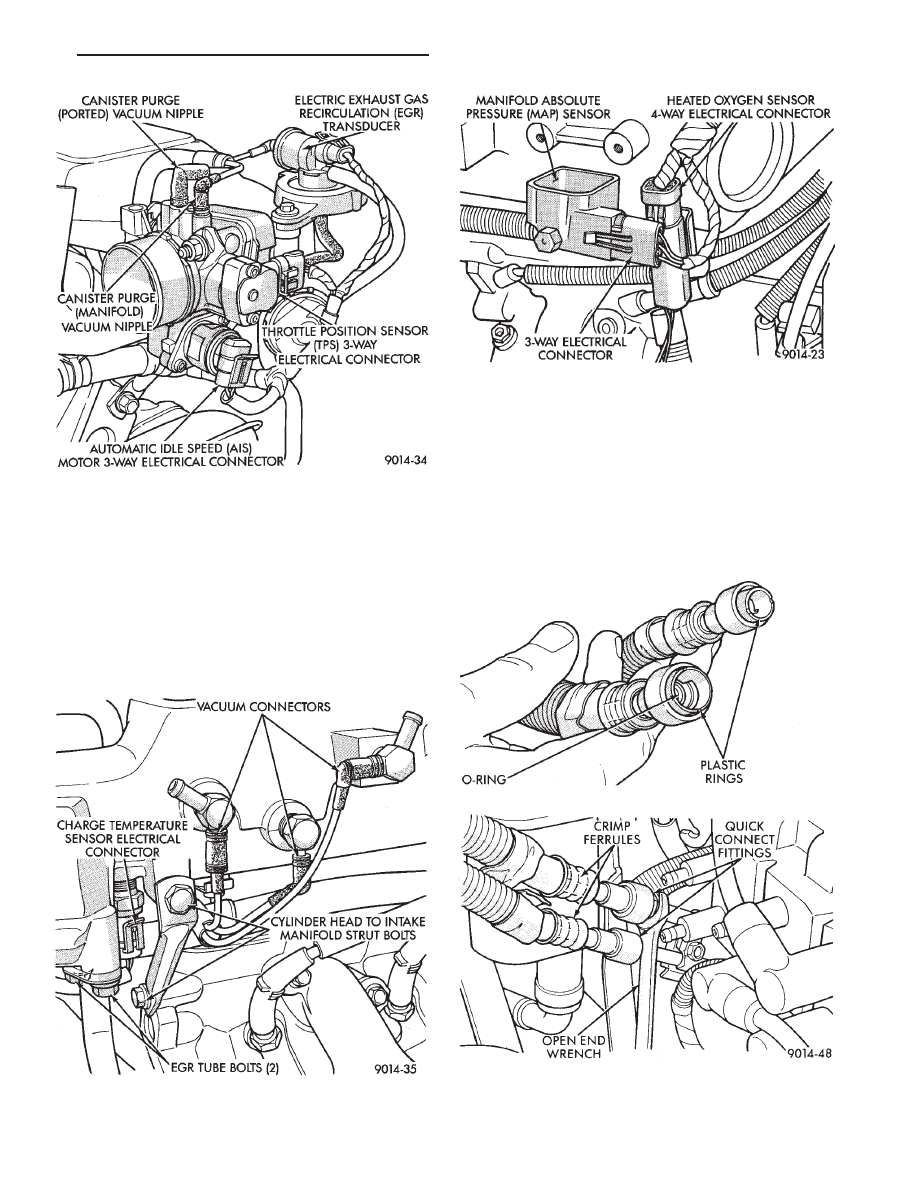
(12) Remove the fuel hose quick connect fittings

from the fuel rail by using an open end wrench pushing
in on the plastic ring located on the end of the fittings.
Gently pull the fittings from the fuel rail (Fig. 7).

WARNING: WRAP A SHOP TOWEL AROUND HOSES
TO CATCH ANY GASOLINE SPILLAGE DURING RE-
MOVAL.

(13) Remove direct ignition system (DIS) coils and

alternator bracket to intake manifold bolt (Fig. 8).

(14) Remove intake manifold bolts and rotate mani-

fold back over rear valve cover (Fig. 9).

(15) Cover intake manifold with suitable cover when

servicing (Fig. 10).

(16) Remove vacuum harness connector from Fuel

Pressure Regulator.

Fig. 4 Electrical and Vacuum Connection to Throttle

Body

Fig. 5 Electrical and Vacuum Connections To Intake

Manifold

Fig. 6 MAP Sensor Electrical Connector

Fig. 7 Quick Connect Fuel Fittings to Fuel Rail

.

EXHAUST SYSTEM AND INTAKE MANIFOLD

11 - 13

(17) Remove fuel tube retainer bracket screw and

fuel rail attaching bolts (Fig. 10). Spread the retainer
bracket to allow fuel tube removal clearance.

(18) Remove fuel rail injector wiring clip from the

alternator bracket (Fig. 11).

(19) Disconnect cam sensor, coolant temperature

sensor, and engine temperature sensors (Fig. 11).

(20) Remove fuel injector wiring clip from intake

manifold water tube.

(21) Remove fuel rail. Be careful not to damage the

rubber injector O-rings upon removal from their ports
(Fig. 12).

(22) Remove upper radiator hose, bypass hose and

rear intake manifold hose (Fig. 13).

(23) Remove intake manifold bolts. Remove intake

manifold.

(24) Remove intake manifold seal retainers screws

(Fig. 14). Remove intake manifold gasket.

INSPECTION

Check for:

• Damage and cracks of each section.

• Clogged water passages in end crossovers.

INSTALLATION

(1) Clean all surfaces of cylinder block and cylinder

heads.

(2) Place a drop (approximately 1/4 in. diameter) of

Mopar Silicone Rubber Adhesive Sealant or equivalent,
onto each of the four manifold to cylinder head gasket
corners (Fig. 15).

Fig. 8 Ignition Coils

Fig. 9 Intake Manifold Bolts

Fig. 10 Fuel Rail Attaching Bolts

Fig. 11 Fuel Injector Wiring Clip

11 - 14

EXHAUST SYSTEM AND INTAKE MANIFOLD

.

WARNING: INTAKE MANIFOLD GASKET IS MADE OF
VERY THIN METAL AND MAY CAUSE PERSONAL
INJURY, HANDLE WITH CARE.

(3) Carefully install the intake manifold gasket (Fig.

14). Torque end seal retainer screws to 12 N

Im (105 in.

lbs.).

(4) Install intake manifold and (8) bolts and torque

to 1 N

Im (10 in. lbs.). Then retorque bolts to 22 NIm

(200 in. lbs.) in sequence shown in (Fig. 13). Then
retorque again to 22 N

Im (200 in. lbs.). After intake

manifold is in place, inspect to make sure seals are
in place.

(5) Make sure the injector holes are clean and all

plugs have been removed.

(6) Lube injector O-ring with a drop of clean engine

oil to ease installation.

(7) Put the tip of each injector into their ports. Push

the assembly into place until the injectors are seated in
the ports (Fig. 12).

(8) Install the (4) fuel rail attaching bolts and torque

to 22 N

Im (200 in. lbs.) (Fig. 10).

(9) Install fuel tube retaining bracket screw and

torque to 4 N

Im (35 in. lbs.) (Fig. 10).

(10) Reconnect cam sensor, coolant temperature sen-

sor and engine temperature sensors (Fig. 11).

(11) Install fuel injector harness wiring clips on the

alternator bracket and intake manifold water tube
(Fig. 11).

(12) Connect fuel pressure regulator vacuum line.
(13) Remove covering on lower intake manifold and

clean surface.

(14) Place intake manifold gasket on lower manifold.

Put upper manifold into place and install bolts finger
tight.

(15) Install the alternator bracket to intake mani-

fold bolt and the cylinder head to intake manifold strut
bolts. (Do not torque.)

Fig. 12 Fuel Rail Removal

Fig. 13 Intake Manifold Removal and Installation

Fig. 14 Intake Manifold Gasket

Fig. 15 Intake Manifold Gasket Sealing

.

EXHAUST SYSTEM AND INTAKE MANIFOLD

11 - 15

(16) Torque intake manifold bolts to 28 N

Im (250 in.

lbs.) following torque sequence in (Fig. 9).

(17) Torque alternator bracket to intake manifold

bolt to 54 N

Im (40 ft. lbs.) (Fig. 8).

(18) Torque the cylinder head to intake manifold

strut bolts to 54 N

Im (40 ft. lbs.) (Fig. 5).

(19) Connect ground strap, MAP and heated oxygen

sensor electrical connectors (Fig. 6).

(20) Connect charge temperature sensor electrical

connector (Fig. 5).

(21) Connect vacuum harness to intake plenum (Fig.

5).

(22) Using a new gasket, connect the EGR tube

flange to the intake manifold and torque to 22 N

Im

(200 in. lbs.).

(23) Clip wiring harness into the hole in the throttle

cable bracket.

(24) Connect the wiring connectors to the throttle

position sensor (TPS) and Automatic Idle Speed (AIS)
motor (Fig. 4).

(25) Connect vacuum harness to throttle body (Fig.

4).

(26) Install the direct ignition system (DIS) coils.

Torque fasteners to 12 N

Im (105 in. lbs.) (Fig. 8).

(27) Lubricate the ends of the chassis fuel tubes with

30 wt. oil. Connect fuel supply and return hoses to
chassis fuel tube assembly. Pull back on the quick
connect fitting to ensure complete insertion (Fig. 7).
(Refer to Fuel Hoses, Clamps and Quick Connect
Fittings in Group 14 Fuel Systems).

(28) Install throttle cable (Fig. 3).
(29) Connect fuel injector wiring harness.
(30) Install air cleaner and hose assembly (Fig. 2).
(31) Connect negative battery cable. Fill Cooling

System. See Cooling System, Group 7.

(32) With the DRB II use ASD Fuel System Test to

pressurize system to check for leaks.

CAUTION: When using the ASD Fuel System Test,
The Auto Shutdown (ASD) Relay will remain ener-
gized for 7 minutes or until the ignition switch is
turned to the OFF position, or Stop All Test is se-
lected.

EXHAUST MANIFOLDS

REMOVAL

(1) Raise vehicle and disconnect exhaust pipe from

rear (cowl side) exhaust manifold at articulated joint.

(2) Separate EGR tube from rear manifold and dis-

connect Heated Oxygen Sensor lead wire (Fig. 16).

(3) Remove

Alternator/Power

Steering

Support

Strut (Fig. 16).

(4) Remove bolts attaching cross-over pipe to mani-

fold (Fig. 16).

(5) Remove bolts attaching rear manifold to cylinder

head and remove manifold.

(6) Lower vehicle and remove screws attaching front

heat shield to front manifold (Fig. 17).

(7) Remove bolts fastening crossover pipe to front

exhaust manifold and nuts fastening manifold to cyl-
inder head. Remove assemblies (Fig. 18).

INSPECTION

Inspect exhaust manifolds for damage or cracks and

check distortion of the cylinder head mounting surface
and exhaust crossover mounting surface with a
straightedge and thickness gauge (Fig. 19).

INSTALLATION

(1) Install rear exhaust manifold and tighten attach-

ing bolts to 23 N

Im (200 in. lbs.).

(2) Attach exhaust pipe to exhaust manifold and

tighten shoulder bolt to 28 N

Im (250 in. lbs.).

(3) Attach crossover pipe to exhaust manifold and

tighten bolt to 33 N

Im (25 ft. lbs.) and connect oxygen

sensor lead (Fig. 16).

Fig. 16 EGR Tube, Heated Oxygen Sensor and

Alternator/Power Steering Strut

Fig. 17 Heat Shield

11 - 16

EXHAUST SYSTEM AND INTAKE MANIFOLD

.


Content   ..  8  9  10  11   ..