Content .. 1060 1061 1062 1063 ..
Chevrolet Silverado / GMC Sierra. Manual - part 1062

Fig. 141: View Of Valve Body To Transmission Case
Courtesy of GENERAL MOTORS CORP.
6. Install the valve body to the transmission case while simultaneously connecting the manual
valve link to the manual valve.
2008 Chevrolet Silverado 1500
2008 TRANSMISSION Automatic Transmission - 4L60-E/4L65-E/4L70-E - Cab & Chassis Sierra, Cab & Chassis
Silverado, Sierra & Silverado
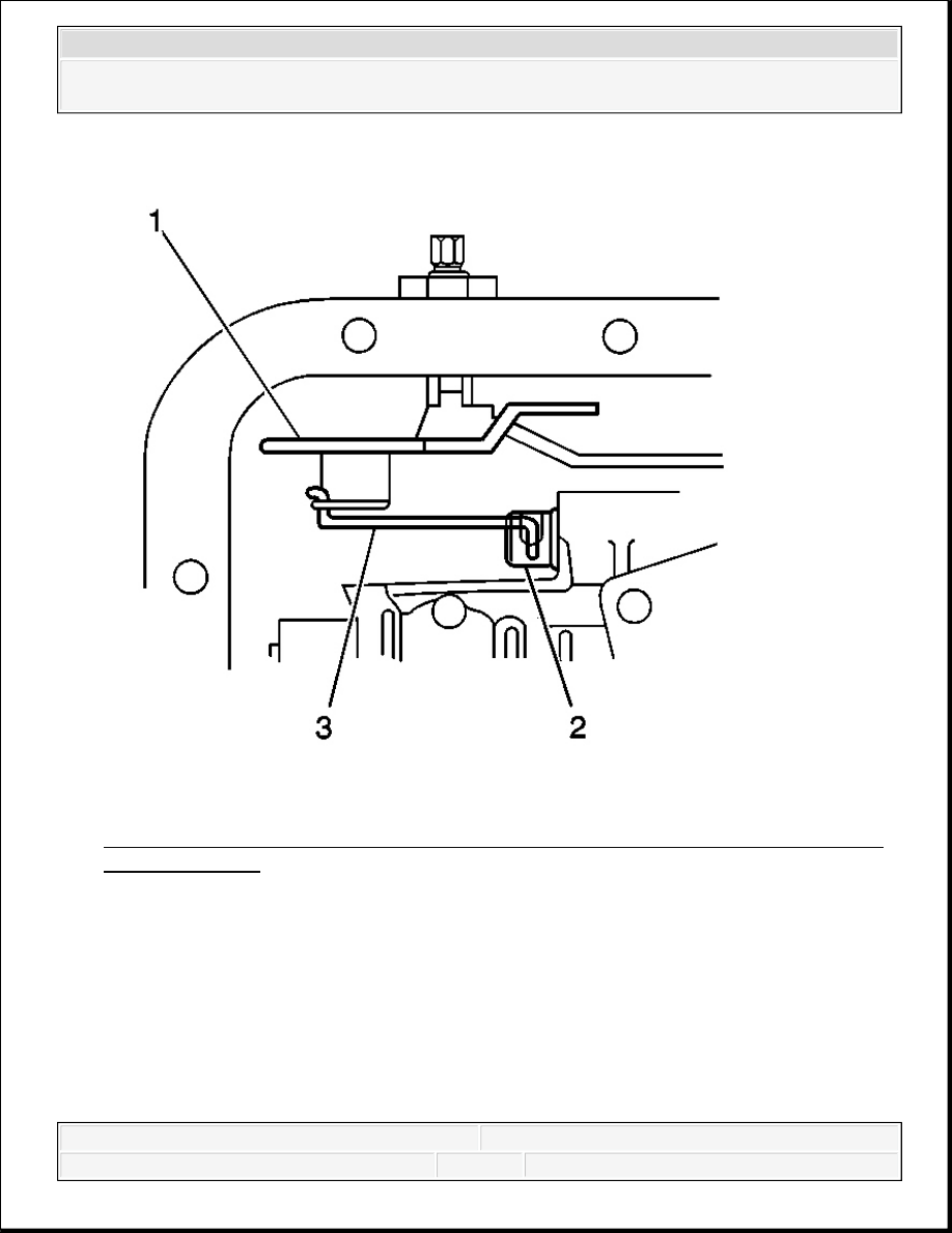
Fig. 142: Verifying Manual Valve Link Is Installed Properly To Inside Detent Lever
& Manual Valve
Courtesy of GENERAL MOTORS CORP.
7. Verify that the manual valve link (3) is installed properly to the inside detent lever (1) and
the manual valve (2).
2008 Chevrolet Silverado 1500
2008 TRANSMISSION Automatic Transmission - 4L60-E/4L65-E/4L70-E - Cab & Chassis Sierra, Cab & Chassis
Silverado, Sierra & Silverado

Fig. 143: Installing One Bolt (M6 X 1.0 X 47.5) Hand Tight In Center Of Valve Body
Courtesy of GENERAL MOTORS CORP.
8. Install one bolt (M6 X 1.0 X 47.5) hand tight in the center (1) of the valve body to hold it in
place.
2008 Chevrolet Silverado 1500
2008 TRANSMISSION Automatic Transmission - 4L60-E/4L65-E/4L70-E - Cab & Chassis Sierra, Cab & Chassis
Silverado, Sierra & Silverado

Fig. 144: Identifying Valve Body Bolts
Courtesy of GENERAL MOTORS CORP.
9. Do not install the transmission fluid indicator stop bracket and bolt at this time.
Install but do not tighten the valve body bolts which retain only the valve body directly.
Each numbered bolt location corresponds to a specific bolt size and length, as indicated by
the following:
IMPORTANT: When installing bolts throughout this procedure, be sure to
use the correct bolt size and length in the correct location as
specified.
2008 Chevrolet Silverado 1500
2008 TRANSMISSION Automatic Transmission - 4L60-E/4L65-E/4L70-E - Cab & Chassis Sierra, Cab & Chassis
Silverado, Sierra & Silverado
Content .. 1060 1061 1062 1063 ..