Chery Tiggo T11 LHD. Manual - part 90
T11 Service Manual Transmission
102
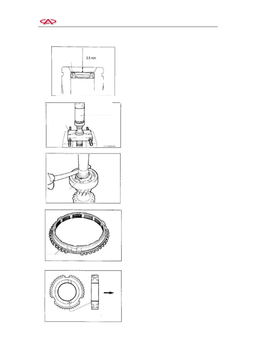
3. Assembly
1) Installation
of
seal-input
shaft
oil-collecting hole
Press in the seal till the dimension shown in
the left figure is obtained.
2) Installation of input shaft front bearing
3) Installation of snap ring-input shaft front
shaft
Select the thickness of snap ring to make the
axial clearance of input shaft front bearing
conform to the standard.
The standard value: 0.01 mm to 0.12 mm
4) Installation of synchronizer spring
Install the synchronizer spring on the
specified position of the synchronizer ring,
shown in the left figure.
5) Installation of gear hub-3
rd
-4
th
gear
Install the gear hub-3
rd
-4
th
gear in the
direction shown in the left figure.
Snap ring
Synchronizer Spring
Rear of
transmission