Chery Tiggo T11 LHD. Manual - part 88


  Index      Chery     Chery Tiggo T11 LHD - service repair manual


Search            


Content   ..  86  87  88  89   ..


Chery Tiggo T11 LHD. Manual - part 88


T11 Service Manual                                                Transmission 

94 


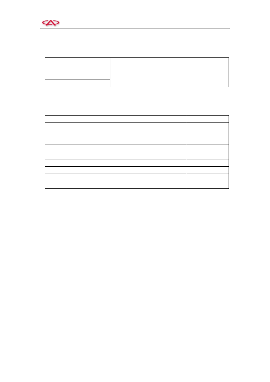
7. Lubricating Grease 

Item 

Specified Lubricating Grease 

Drive shaft seal lip 

Mobilux Ep2 

Input shaft seal lip 

Selector lever support cushion 


8. Torque Specification 


Item 

Torque N.m (kgf) 

Bottom cap-Transmission installation bolts 

6.2~7.6 

Clutch box-Transmission housing installation bolts 

39.5~48.5 

Clutch release bearing saddle retainer installation bolts 

8.8~10.8 

Gear-shifting mechanism assembly installation bolts 

16.1~19.9 

Gear-shifting staying wire bracket installation bolts 

16.1~19.9 

Speedometer gear installation bolts 

3.5~4.3 

Main gearbox driven gear installation bolts 

118.5~145.5 

Backup lamp switch 

28.7~35.3 

Idling gear assembly installation bolts 

43.1~52.9 


T11 Service Manual                                                Transmission 

95 

Section    Removal and Installation   

1. External Structural Diagram of QR523 Transmission 


Clutch hydraulic oil pipeline assembly 

Clutch housing assembly 

Release fork 

Release fork dustproof boot 

Gear-shifting  mechanism 

assembly 

Stud bolt 

Bearing cap assembly 

Transmission  housing 

assembly 

T11 Service Manual                                                Transmission 

96 

2. Removal and Installation of Main Parts 

(1) Removal   


1)  Removal of transmission housing 

Remove  the  gear-shifting  mechanism  assy., 

bearing  cap  assy.,  snap  ring-output  shaft  front 

bearing,  bottom  cap-transmission  and  reverse 

gear idling gear assembly, and then remove the 

transmission housing. 


2)  Removal  of  3

rd

-4

th

  gear  shifting  fork 

rail/3

rd

-4

th

  gear  shifting  fork/5

th

-reverse 

gear  shifting  fork  rail/5

th

-reverse  gear 

shifting fork 

a.  Move  the  3

rd

-4

th

  gear-shifting  fork 

and  5

th

-reverse  gear-shifting  fork  in 

the  directions  shown  in  the  left 

figure. 


b.  Slide  the  fork  stalk–3

rd

-4

th

  gear  and 

fork  stalk–5

th

-reverse  gear  in  the 

directions  shown  in  the  left  figure, 

and  disassemble  them  together  with 

the shift fork.   


2)  Removal of input/output shaft 

Remove  the  input  shaft  together  with  the 

output shaft. 


Bottom cap of   
Transmission 

3

rd

-4

th

 gear   

shifting fork 

5

th

-reverse  gear 

shifting fork 

Input 

shaft 

assembly 

Output 

shaft 

assembly 

Fork stalk – 
3

rd

-4

th

 gear   

Fork stalk – 
5

th

-reverse gear 

T11 Service Manual                                                Transmission 

97 

(2) Adjustment before Installation   


Select  the  thickness  of  washer  to  adjust  the 

differential pretension 

1)  Place  the  tin  solder  sheet  (approx.  10  mm 

long and 1.6 mm diameter) on the specified 

part  of  transmission  housing,  and  then 

install  the  outer  race  of  bearing  and  the 

differential. 

2)  Install the clutch box, and tighten the bolt to 

the specified torque. 

3)  Replace these tin solder sheets with  thicker 

tin  solder  sheets  if  these  sheets  aren’t 

flattened.  And  then  repeat  these  steps  (1) 

and (2). 

4)  Apply a micrometer calipers to measure the 

thickness  (T)  of  the  flattened  tin  solder 

sheet. 

5)  Select  the thickness  of  washer that shall be 

installed  according 

to  the  following 

equation. 

Thickness of washer: 

(T+0.005 mm)~ (T+0.11 mm) 


(3) Installation   


1)  Installation of input/output shaft 

Install the input shaft together with the output 

shaft. 


2)  Installation  of  the  5

th

-reverse  gear  shifting 

fork/fork  stalk–5

th

-reverse  gear  fork/3

rd

-4

th


gear shifting fork/fork stalk–3

rd

-4

th

 fork 

a.  Move  the  gear  bush–3

rd

-4

th

  gear  and 

the  gear  bush–5

th

-reverse  gear  in  this 

direction shown in the left figure. 

Input shaft 

Output shaft 

Gear bush – 
3

rd

-4

th

 gear 

Gear bush – 
5

th

-reverse gear 

Tin solder sheet 


Content   ..  86  87  88  89   ..