Chery Tiggo T11 LHD. Manual - part 87
T11 Service Manual Transmission
90
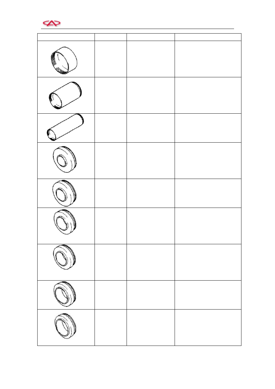
Tool
Symbol
Name
Application
MB998812
Installer Cap
Apply this cap together with
the installer and the installer
connector
MB998813
Installer (100)
Apply this installer together
with the installer cap and the
installer connector
MB998814
Installer connector
(200)
Apply this installer together
with the installer cap and the
installer connector
MB998816
Installer connector
(30)
To install the front bearing of
input shaft
MB998817
Installer connector
(34)
To install the rear bearing of
output shaft
MB998818
Installer connector
(38)
To uninstall the bearing of
input shaft, inner race of
bearing, reverse gear, needle
bearing and bush – the bearing
of reverse gear
MB998819
Installer connector
(40)
To install the bush- 5
th
-reverse
gear synchronizer, front/rear
bearing of differential, and
bush – 4
th
gears and bush – 5
th
gears
MB998822
Installer connector
(46)
To install the bush – the 1
st
gears and bush – the 2
nd
gears
and 3
rd
gears
MB998823
Installer connector
(48)
To install the inner race of
differential’s bearings and the
bearing of differential