Chery Tiggo T11 LHD. Manual - part 82
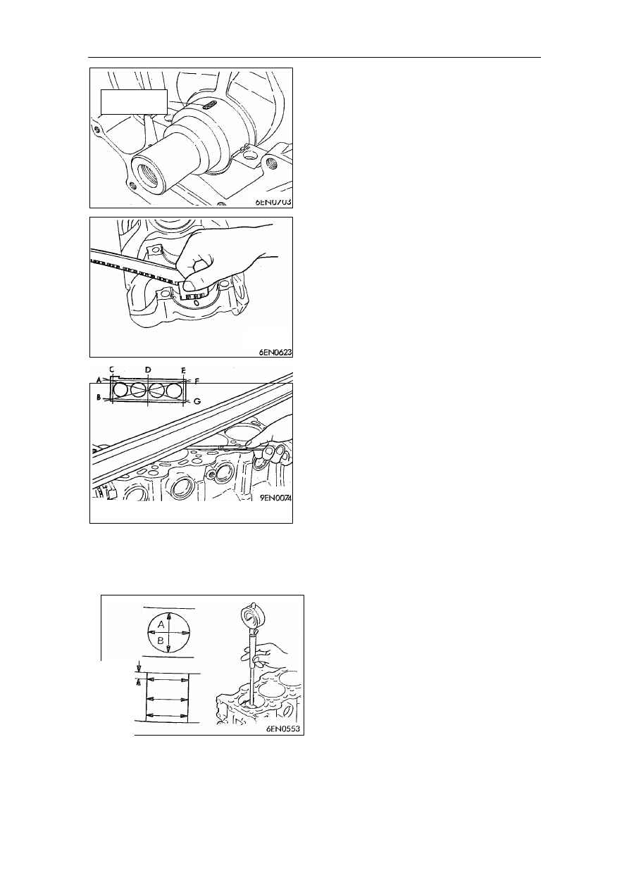
Check
Oil
clearance
of
crankshaft
(Plastigauge )
(1) Clean the oil on main journal and
internal diameter of bearing out.
(2) Install crankshaft.
(3) Divide plastigauge into the same
length of bearing width and put it on
crankshaft journal and make it
parallel to axle center line.
(4) Install main bearing cap carefully,
and screw nuts on according to the
regulated torque.
(5) Disassemble main bearing cap
carefully.
(6) Use measuring rule imprinted on the
package of plastigauge to measure
the width of the widest part of
staved plastic line and get clearance
value.
Standard value:0.02~0.04mm
Limit value:0.1mm
Cylinder block
(1) Observe if there are defects like
scratch, rust and corrosion with eyes.
Use defect detector to check breach.
If any, fix or replace it.
(2) Check if the surface of cylinder
block warps and assure there’s no
pad scraps or other foreign matters.
Standard value:0.05mm
Limit value:0.1mm
(3) If warping excessively, revise or
replace it within the permitting
range.
Abrasive limit:0.2mm
Maximum
sum
of
abrasive
thickness of cylinder block and
cylinder cap permitted is o.2mm.
Height of cylinder block(new):
4G63 284mm, 4G64 290mm
(4) Check if there’s scratch and cylinder
sticking. If it’s disqualified, revise
(increase the size) or replace it.
(5) Check internal diameter of cylinder
and cylindricality with cylinder bore
gauge.
Revise cylinder according to increased
diameter, replace piston and piston ring if
wearing badly. Checking position as shown.
Standard value:
internal diameter of cylinder
4G63 85.00~85.03mm
4G64 86.50~86.53MM
plastigaug
e
12mm
m
center
bottom