Chery Tiggo T11 LHD. Manual - part 81


  Index      Chery     Chery Tiggo T11 LHD - service repair manual


Search            


Content   ..  79  80  81  82   ..


Chery Tiggo T11 LHD. Manual - part 81


Service Manual for Chery·Tiggo (T11)  Engine Section 


Piston and Connecting Rod Component Installation 

(1)  Daub enough engine oil on  piston, compression 

ring and oil control ring. 

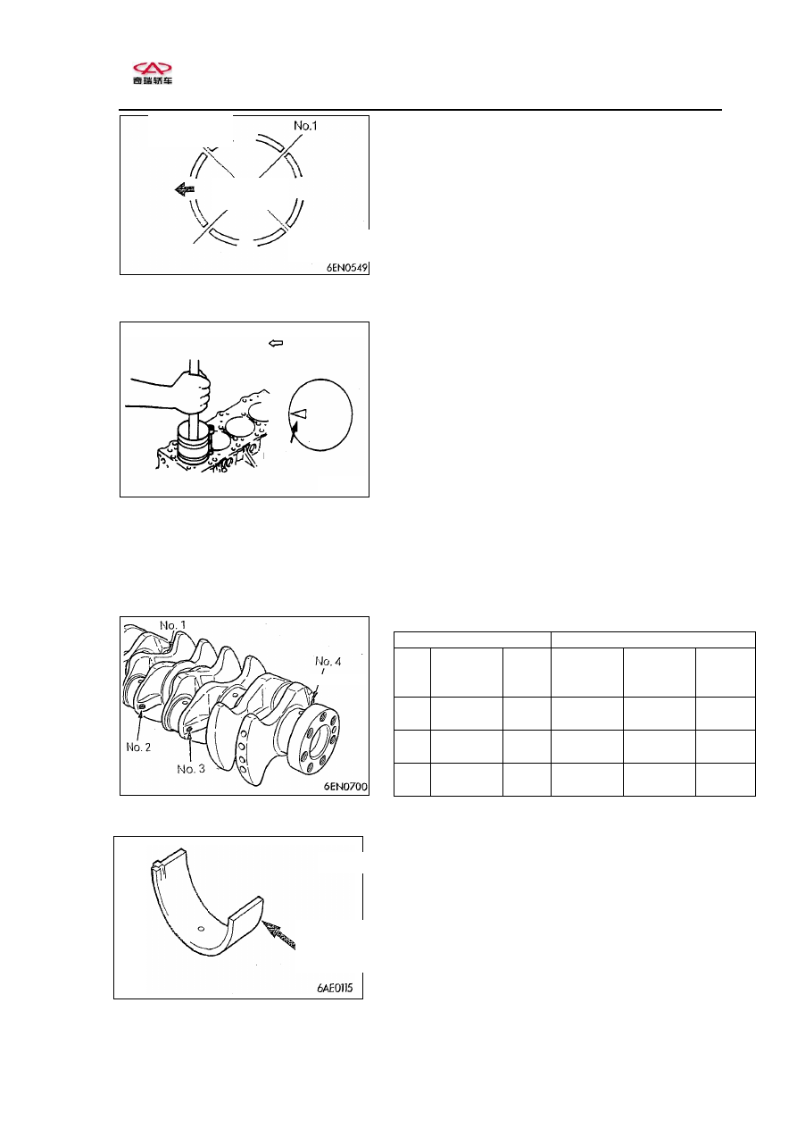
(2)  Adjust open position of compression ring and 

oil  control  ring  (blade  and  main  ring)  to  the 
position as shown. 

(3)  Rotate  crankshaft  to  make  crank  pin  located  in 

the middle of cylinder   


(4)  Before  inserting  piston  and  connecting  rod 

component into cylinder, proper screw-mounted 
protector  is  applied  in  connecting  rod  bolt.  Be 
careful and don’t damage crank pin. 

(5)  Use  suitable  piston  ring  compressor  to  insert 

piston  and  connecting  rod  component  into 
cylinder. 

Caution: 

·There’s a forward mark on the top of piston, 

make  it  point  to  straight  position  of  the 
engine (the side of timing belt). 

Connecting Rod Bearing Installation 
If  it  is  necessary  to  replace  bearing,  choose  and 
install bearing according to the following steps.   
(1)  Measure  external  diameter  of  crank  pin  and 

confirm  the  groups  according  to  the  following 
table. 

As 

crankshaft 

for 

maintenance, 

distinguish  sizes  by  painting  color  in  the 
position as shown. 

 
(2)  Identification mark of connecting rod bearing is 

imprinted in the position as shown. 

Crank pin 

Connecting rod bearing 

Groups 

Identification 

color 

External 

diameter 

(mm) 

Identification 

mark 

Identification 

color 

Thickness 

(mm) 

Ⅰ 

Yellow 

44.995~

45.000 

Yellow 

1.487~

1.491 

Ⅱ 

Nil 

44.985~

44.995 

Nil 

1.491~

1.495 

Ⅲ 

White 

44.980~

44.985 

Blue 

1.495~

1.499 


Internal diameter of connecting rod:48.000~48.015mm 


(3)  Choose bearing in the table above, according to 

groups assured in (1) and (2). 
Examples for choosing bearing: 
If measurement value of external diameter of 
crankshaft pin is 44.996mm , it shall be Group 1 
in  the  table  above.  If  replacing  crankshaft  of 
maintenance,  check  identification  color  applied 
on new crankshaft pin. If it’s yellow, crankshaft 
pin shall be Group 1 and choose connecting rod 
bearing of which identification mark is 1.       


Direction 

mark 

Timing  belt 

side 

Side  of  the 
crankshaft 
pulley 

R2 open and 

main 

ring 

open 

Upper blade 

Lower blade 

Piston pin 

identification 

mark 


Service Manual for Chery·Tiggo (T11)  Engine Section 


Installation of Connecting Rod Cap 
(1)  When installing connecting rod cap, check 

marks  of  disassembling.  If  installing  new 
parts  which  have  no  marks,  install 
anti-rotating gap as shown on one side. 


(2)  Ensure  if  axial  clearance  of  big  end  of 

connecting rod is suitable. 
Standard value:0.10~0.25mm 
Limit value:0.4mm 


Connecting Rod Nut Installation 
Caution: 
  Before  installing  connecting  rod  cap, 

disassemble 

spark 

plug 

and 

install 

connecting  rod  nut,  if  having  installed 
cylinder cap.   

(1)  As  for  connecting  rod  nut  and  bearing, 

plastic-zone  screw-on  method  shall  be 
adopted.  Before  reusing  the  bearing,  check  if 
the  bearing  is  expanded.  Checking  method: 
screw  nuts  into  screw  thread  of  bearing  with 
fingers till the whole length of screw thread. If 
nuts  can’t  be  screwed  on  smoothly,  screw 
thread  may  be  expanded  and  bearing  should 
be replaced.         

(2)  Before  screwing  nuts  on,  daub  oil  on  screw 

thread of nuts and seat surface. 

(3)  Screw  nuts  into  bearing  with  fingers  and 

screw  nuts  on  alternatively  to  install 
connecting rod cap correctly. 

(4)  Screw nuts on by torque of 20N.M. 
(5)  Daub paint mark on every nut head. 
(6)  Daub  paint  mark  on  bolts  of  which  the 

position  is  from  paint  mark  on  every  nut 
head to screwing direction of90~100°and 
note down the paint mark.   

(7)    Screw nuts on from 90~100°until marks 

on nuts and bearing are aligned.   
Caution: 
  If  screwing  angle  is  less  than  90°

screwing  specified  capability  can’t 
be  assured.  When  screwing  it  on, 
notice screwing angle. 

  If  screwing  nuts  are  excessively 

tightened  (exceed  angle  of  100°)  , 
screw nuts off totally. And restart to 
screw nuts from step 1   

油漆 
标记 

油漆标记 

cylinder 

number


anti-rotating 

gap


paint mark 

paint 

mark 


Service Manual for Chery·Tiggo (T11)  Engine Section 


Check 

Piston ring 

(1)  Check  if  there’s  damage,  excessive  wear  and 

breach  on  piston  ring.  If  any,  replace  it.  If 

replacing  piston,  it  is  necessary  to  replace 

piston ring.   

(2)  Check clearance between piston ring and piston 

ring groove. If it’s too wide, replace piston ring 

or both of them. 

Standard value: 0.02~0.06mm 
Limit value: 0.1mm 


(3)  Put  piston  ring  into  cylinder.  After  using  top 

surface  of  piston  to  put  it  away,  measure  open 

clearance  with  clearance  gauge.  When  open 

clearance is too wide, replace piston ring. 

Standard value: 

No.1 ring…0.25~0.35mm 

        No.2 ring…0.40~0.55mm 
        Oil control ring…0.10~0.40mm 
Limit value: 

No.1 ring and No.1 ring…0.8mm 

 Oil control ring…1.0mm 


Oil clearance of crank pin (Plastigauge ) 

(1)  Clean  the  oil  on  connecting  rod  neck  and 

bearing out. 

(2)  Divide  plastigauge  into  the  same  length  of 

rearing width and put it on crank pin and make 

it parallel to axle center line. 

 
(3)  Install  connecting  rod  cap  carefully,  and  screw 

nuts on according to the regulated torque.    

(4)  Disassemble connecting rod cap carefully. 

(5)  Use measuring rule imprinted on the package of 

plastigauge  to  measure the  width  of the widest 

part  of  staved  plastic  line  and  get  clearance 

value. 

Standard value:0.02~0.05mm 
Limit value:0.1mm 


press in with piston 

open clearance


piston ring 

plastigauge 


2 、

Crankshaft,  cylinder  block  and 

flywheel 


Disassembling steps 

1. 

Screw rearing of flywheel<M/T> 

2. 

Jointing board<M/T> 

3. 

Flexible flywheel<M/T> 

4. 

Jointing board<M/T> 

5. 

Crankshaft bushing<M/T> 

6. 

Rear cover board 

7. 

Bell housing 

8. 

Rear oil seal cap 

9. 

Rear oil seal 

10.

Main bearing cap bolt


Daub  engine  oil  on 

all  the  operation 

parts 

when 

installing.


8.8N.m 

16 

15 

14 

13 

12 

11 

10 

25N.m+90

o

to10

0

Disassembling 
illustration 

2.5kgf.m 

11.

Main bearing cap 

12.

 Lower bearing of crankshaft 

13.

Crankshaft 

14.

Upper bearing of crankshaft 

15.

Crankshaft thrust rearing 

16.

Cylinder block 

17.

Drive board〈A/T〉 

18.

Crankshaft sleeve〈A/T〉 

18.

Jointing board〈A/T〉 

19.

Driving board bolt

〈A/T〉 


17 

20 

19 

18 


Content   ..  79  80  81  82   ..