Chery Tiggo T11 LHD. Manual - part 80
Service Manual for Chery·Tiggo (T11) Engine Section
Chapter 4 Crank Connecting Rod Mechanism
1、
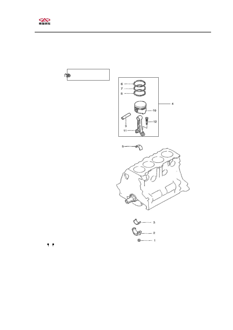
Piston and connecting rod component
Daub oil on all the
inner
parts
when
installing.
Disassembling steps
1.
Connecting rod nut 2、Connecting rod cap 3、Connecting rod bearing
4、Piston and connecting rod component
5、 Connecting rod bearing 6、No.1 compression ring 7、No.2 compression
ring 8、Oil control ring
9、 Piston pin 10、Piston 11、Connecting rod 12、Connecting
rod bolt