Chery Tiggo T11 LHD. Manual - part 76


  Index      Chery     Chery Tiggo T11 LHD - service repair manual


Search            


Content   ..  74  75  76  77   ..


Chery Tiggo T11 LHD. Manual - part 76


(5)

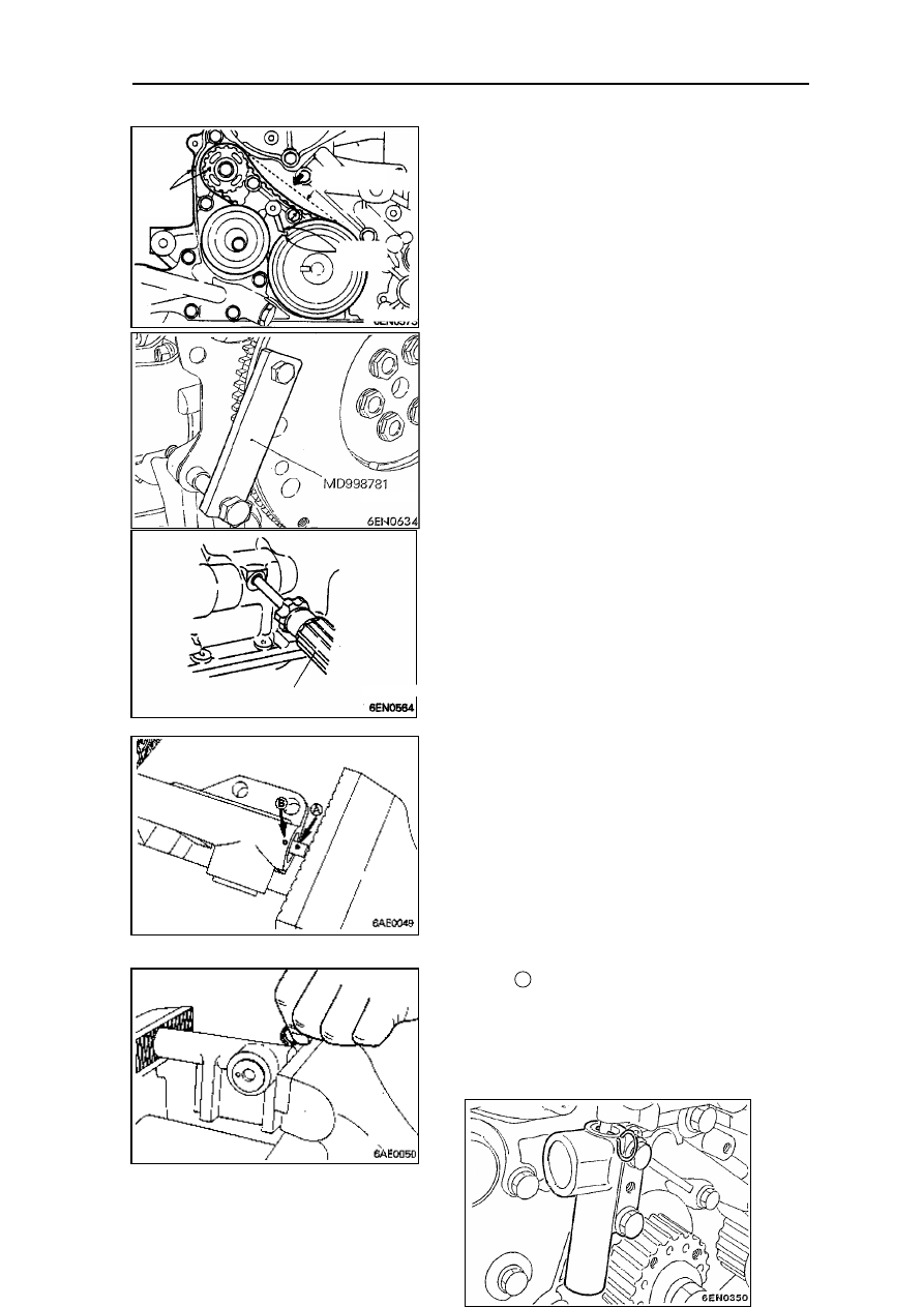
Ensure to  keep the marks in the pulley and the

front cover aligned.

(6)

Press the central part in the side of tensioner of

the timing belt B with the index finger, with the
pressure limit of 5

~7mm.

Fasten the crankshaft bolt

(1) Fix the flywheel with special tool.
(2) Install crankshaft bolt.

Installation of pulley in oil pump

(1) Insert cross-ended screwdriver to the left side

of   hole   in   the   cylinder   to   prevent   turning   of
balance shaft.

(2) Install pulley of oil pump.
(3) Apply oil to the combining side of screw nut

and bearing.

(4) Fasten the screw nut with a torque of 54Nm.

Installation of automatic tensioner

(1) If   the   automatic   tensioner   is   in   the

stretching   position,   it   should   be   drawn
back according to the following steps. 

(2) Fasten the automatic tensioner with vises

that have soft opening.
Caution:
·As there is a stretching screw plug at

the bottom of automatic tensioner, a
plain pad should be inserted between
the   vises   and   the   screw   plug   to
prevent their direct contact.

(3) Slowly push the vises in until the rod hole

and oil tank  gets aligned.

(4) Insert   the   steel   wire(diameter   1.4mm)   to

the aligned hole.

(5) Disassemble the automatic tensioner from

the vises.

timing 

mark

Belt  pressure 

limit

timing 

mark

A

(6) Install   the   automatic

tensioner in the front cover,
fastening   the   bolt   with   a

torque of 24Nm.
Caution:
·Leave   the   steel   wire   in   the
automatic tensioner.

Installation of tensioning pulley

(1)Install the tensioning pulley and keep the

two pin holes in a vertical line.

Installation of timing belt

(1) Make   sure   that   the   belt   tensioner   is

installed properly.

(2) Make the timing mark in the camshaft

pulley   and   that   in   the   cylinder   cover
aligned.

(3) Make the timing mark in the crankshaft

pulley   and   that   in   the   front   cover
aligned.

(4) Keep the timing mark in the oil pump

pulley and its conforming mark aligned.

螺 丝 刀
screwdriv
er

Pinhole

Timing mark

Timing mark

Timing mark

(5) Disassemble   the   plug   from   the   cylinder

block   and   then   insert   the   cross-ended
screwdriver (diameter of8mm) to the hole.
If it could be inserted more than 60mm in, it
means that the timing marks are aligned. If

the   range   that   could   not  be   inserted     above  20

25mm, the oil pump pulley should be turned for one
revolution   and   the   timing   marks   should   be   then
aligned.   Again   check   if   the   screwdriver   could   be
inserted   over   60mm.   Keep   the   screwdriver   in   the
inserting position until the installation of belt finishes.

(6)Connect   the   timing   belt   to   the   crankshaft   pulley,

middle pulley, camshaft pulley and tensioner pulley in
turn.

(7)

Raise   the   pulley   of   the   tensioner   to   the

direction of arrow and then fasten the central bolt. 

(8)

Make   sure   that   all   the   timing   marks   are

aligned.

(9) Disassemble   the   screwdriver   inserted   in   step   (5)

and fix the plug.

(10)Rotate counterclockwise the crankshaft for a quarter

of   revolution   until   all   the   timing   marks   again   get
aligned.

(11)Install   the  special  tools  socket   wrench   and   torque

wrench to the tensioner pulley and then loosen the
central bolt in the pulley of tensioner.

Remarks:

If   special   tools   could   not   be   applied,   a   general
torque wrench that could measure a torque of 0 to
0.5 KgM may be used.

(12)Fasten  to the  torque  of 3.5N.m(0.35  KgM)  with  a

torque wrench.

(13)While keeping the tensioner pulley with special tool

and   torque,   fasten   the   central   bolt   to   standard
value.

(14)Rotate clockwise the crankshaft two revolutions and

lay it for about 15minutes. Then check whether the
fixing steel wire of automatic tensioner could slide
freely.

Remarks:
If the steel wire could not slide freely, repeatedly
do the steps after (10) until the steel wire slides.

(15)Take off the fixing steel wire of automatic tensioner.

(16)Measure   the   distance   “A”   (between   the   tensioner

arm and the automatic tensioner itself).

Standard value: 3.8

-4.5mm

plug

screwdriver

II.   Rocker   arm   and

camshaft

Disassembling steps
1.

air flow tube

2.

P.C.V. tube

3.

fuel filler cap

4.

rocker arm cap

5.

pad of rocker arm cap 

6.

oil seal

7.

oil seal

8.

rocker arm and rocker shaft

9.

rocker arm and rocker shaft

10. rocker shaft spring

11.rocker arm A
12.rocker arm B
13.rocker shaft(intake side)
14.hydraulic erect post
15.rocker arm C
16.rocker shaft(exhaust side)

17.hydraulic erect post
18.camshaft

Disassemblin

g illustration


Content   ..  74  75  76  77   ..