Chery Tiggo T11 LHD. Manual - part 53


  Index      Chery     Chery Tiggo T11 LHD - service repair manual


Search            


Content   ..  51  52  53  54   ..


Chery Tiggo T11 LHD. Manual - part 53


Chery T11 Service Manual                    Electric Injection System 

25 

5)  Limp-home 

For some identified important failures, when their duration exceeds the setting stabilized time, 

the  ECU  will  apply  appropriate  software  countermeasure  to  maintain  the  operation  of  the 

engine and enable the vehicle not to stop in its way.   

6)  Failure Alarm 

MT  20U  electronic  fuel  injection  system  is  equipped  with  a  failure  lamp.  When  some 

important  parts, such as the ECU,  intake  manifold absolute  pressure sensor, throttle position 

sensor, coolant temperature sensor, knock sensor, oxygen sensor, fuel injector, two drivers of 

idle actuator stepper motor, A/C relay, fan relay and etc, fail to operate and the corresponding 

failure flags are set, the ECU will enable the failure lamp to flash and give alarm to warn the 

owner of the vehicle that your vehicle has already entered into the failure mode, till the failure 

flag is reset. 

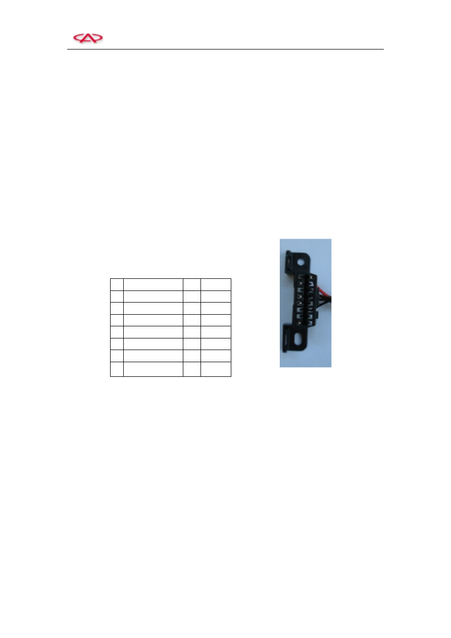
7)  Definition of Diagnosis Connector Interface   


7.   


8)  Failure Readout by Engine Failure Lamp   

When the engine system or its components failure occurs during the operation of engine,  the 

engine failure lamp will light automatically to remind the driver to examine and repair his/her 

vehicle in time. 

During  the  emergency  failure  handling,  you  also  may  conduct  some  special  operations  to 

enable the engine failure lamp to flash frequently so as to read the engine failure code, which 

is the most economical means to obtain the failure code. Its operation method is as follows: 

Examine and Confirm: 

a.  The voltage of battery shall ensure the engine gets its startup speed; 

b.  The engine and the whole vehicle’s accessories shall be in the state of shutdown; 

c.  The throttle is fully closed; 

d.  The transmission is placed in the neutral gear; 


Definition of Diagnosis Connector Interface 

NULL 

16 

+12 V 

Communication 

15 

NULL 

NULL 

14 

NULL 

Earth Wire 

13 

NULL 

Earth Wire 

12 

NULL 

NULL 

11 

NULL 

NULL 

10 

NULL 

Diagnosis 

Request 

NULL 


Chery T11 Service Manual                    Electric Injection System 

26 

e.  The ignition switch is turned off; 

f.  Apply  wires  to  enable  the  diagnosis  request  terminal  1  of  the  failure  diagnosis 

connectors to short circuit with the earth wire terminal 4 or 5

g.  Turn the ignition switch to ON, but don’t start up the engine; 

In this case, if the system  currently  has a  failure  or a history failure code uncleared after 

the failure removal, the engine failure lamp will flash in accordance with a certain rule, and 

the  output system detects the  code  of  failure; (the failure code  is read out and, at the same 

time, the idle control valve will conduct the reset action); 

After  the  completion  of  failure  code  readout,  the  ignition  switch  is  turned  off  and  the 

diagnosis request short-circuit wire is removed; 

The rules that the failure lamp flashes to report the failure are: 

 Report the failure in accordance with the sequence of failure code memorized; 

 3.2 s pause between two failure codes. The digits flash at the frequency of light for 0.4 s 

and extinguish for 0.4s, with 1.2 s pause between two digits; 

 The number 0 flashes10 times, and other numbers corresponds to the flash numbers; 

 Taking the failure code 0110 and 0443 as an example: 


      If the diagnosis request doesn’t interrupt, restart to report 0110 failure code …… 

CAUTION:  After  the  removal  of  failure,  it  is  recommended  to  apply  the  failure  diagnosis 

instrument  to  clear  these  failure  codes  so  as  not  to  make  an  influence  on  the  failure  detection 

during the next repair. 


ISO 9141-2 Standard Diagnosis Connector 


Diagnosis request short circuit to earth 

Turn on the ignition switch 

Failure lamp flashes for one time 

Pause for 3.2s 

10 times 

Pause for 1.2s 

1 time 

Pause for 1.2s 

10 times 

Pause for 3.2s 

10 times 

Pause for 1.2s 

4 times 

Pause for 1.2s 

4 times 

Pause for 1.2s 

3 times 

Pause for 3.2s 


Chery T11 Service Manual                    Electric Injection System 

27 


9)  Removal of Failure Information Record 

After a failure is removed, the failure information record stored in a memory shall be cleared. 

Although  failure  information  has  occurred  when  the  ignition  switch  is  turned  on,  it  isn’t 

recorded if it isn’t kept up to the end of stabilized time. 

After  the  engine  starts  up  successfully  the  specified  times,  the  failure  code  will  be  cleared 

automatically. 

Apply a failure diagnosis instrument and the “Failure Memory Reset” instruction to clear the 

failure information record. 

Pull  out  the  connector  from  ECU  or  remove  the  wires  of  battery  to  clear  the  failure 

information record stored in the external RAM. 

10)  Failure Search 


After  a  failure  information  record  is  obtained  with  the  help  of  the  means  above,  only  the 

approximate location where the failure occurs is known, but it doesn’t mean that the failure is 

found  because  the  reason  to  create  a  failure  information  may  be  the  damage  of  a  electrical 

component (such as sensor or actuator or ECU, etc.), open circuit of a wire, short circuit of a 

wire to earth or the positive electrode of battery, even may be a mechanical fault. 

The  failure  is  inherent,  and  its  external  expressive  results  are  various  kinds  of  symptoms. 

After a symptom is found, it  is required firstly to  use a failure diagnosis instrument or some 

flash codes to check whether there are some failure information records. And, based on these 

information records, the related  failure shall be removed. Then, you can search the failure in 

accordance with the symptom of the engine. 


Diagnosis Interface 

Power Supply 


Chery T11 Service Manual                    Electric Injection System 

28 


2.  Engine Failure Code Table 

Delphi MT 20U Engine Management System Failure Code Table 


Code 

Description 

Code 

Description 

P0105-1  Over-high  intake  manifold  absolute 

pressure sensor signal 

P0443-1  Short-circuit between the wire of canister 

control solenoid valve and the positive of 

electrode power supply   

P0105-2  Too-low 

intake 

manifold 

absolute 

pressure sensor signal 

P0443-2  Open  circuit  of  the  wire  of  canister 

control  solenoid  valve  or short  circuit to 

earth 

P0110-1  Too-low intake temperature sensor signal 

P0480-1  Short  circuit  of  radiator  low-speed  fan 

relay  drive  circuit  to  the  positive 

electrode of power supply 

P0110-2  Over-high  intake  temperature  sensor 

signal 

P0480-2  Open  circuit  of  radiator  low-speed  fan 

relay drive circuit or short circuit to earth 

P0115-1  Too-low  coolant  temperature  sensor 

signal 

P0481-1  Short  circuit  of  radiator  high-speed  fan 

relay  drive  circuit  to  the  positive 

electrode of power supply 

P0115-2  Over-high  coolant  temperature  sensor 

signal 

P0481-2  Open  circuit  of  radiator  high-speed  fan 

relay drive circuit or short circuit to earth 

P0120-1  Over-high throttle position sensor signal 

P0482-1  Short  circuit  of  A/C  cooling  fan  relay 

drive  circuit  to  the  positive  electrode  of 

power supply 

P0120-2  Too-low throttle position sensor signal 

P0482-2  Open  circuit  of  A/C  cooling  fan  relay 

drive circuit or short circuit to earth 

P0130-4  No oxygen sensor signal 

P0500-0  No vehicle speed sensor signal 

P0135-1  Short  circuit  of  oxygen  sensor  heating 

circuit  to the  positive  electrode  of  power 

supply 

P0505-0  Idle control error 

P0135-2  Open  circuit  of  oxygen  sensor  heating 

circuit or short circuit to earth 

P0560-1  Over-high system voltage 

P0170-1  Over-long  oxygen  sensor  indication  of 

time of rich air-fuel-ratio   

P0607-0  Knock control system failure 

P0170-2  Over-long  oxygen  sensor  indication  of 

time of lean air-fuel-ratio   

P0650-1  Short  circuit  between  the  failure  lamp 

wire and the  positive electrode  of  power 

supply 

P0201-0  Fuel  injector  A  (No  1  cylinder)  circuit 

failure 

P0650-2  Open  circuit  of  the  failure  lamp  wire  or 

short circuit to earth 

P0202-0  Fuel  injector  B  (No  3  cylinder)  circuit 

failure 

P1230-1  Short  circuit  of  main  relay  circuit  to  the 

positive electrode of power supply 

P0203-0  Fuel  injector  C  (No  4  cylinder)  circuit 

failure 

P1230-2  Open  circuit  of  main  relay  circuit  or 

short circuit to earth 


Content   ..  51  52  53  54   ..