Chery Tiggo T11 LHD. Manual - part 51


  Index      Chery     Chery Tiggo T11 LHD - service repair manual


Search            


Content   ..  49  50  51  52   ..


Chery Tiggo T11 LHD. Manual - part 51


Chery T11 Service Manual                    Electric Injection System 

17 


Measures on  troubles:  Once  one  ignition  coil 

failure is detected, close the fuel injector of the 

corresponding cylinder. 

CAUTION:  The  over-high  temperature  of 

ignition  coil  may  cause  the  bad  operation  of 

engine ignition system. 

Resistance  of  ignition  coil  primary  winding: 

0.55 to 0.45 KΩ 

Resistance 

of 

ignition 

coil 

secondary 

winding: 5.6 to 4.8 KΩ 

High-voltage side: 

These  pins  No  1,  2,  3  and  4  connect  to  the 

ignition  plugs  of  No  1,  2,  3  and  4  engine 

cylinders respectively via the distribution wire. 

Troubleshooting:   

1)  Short or open circuit inside coil; 

2)  Electricity  leakage  of  coil,  and  crack  of 

casing; 

3)  The  coil  aging  causes  the  shortage  of 

ignition electricity quantity. 


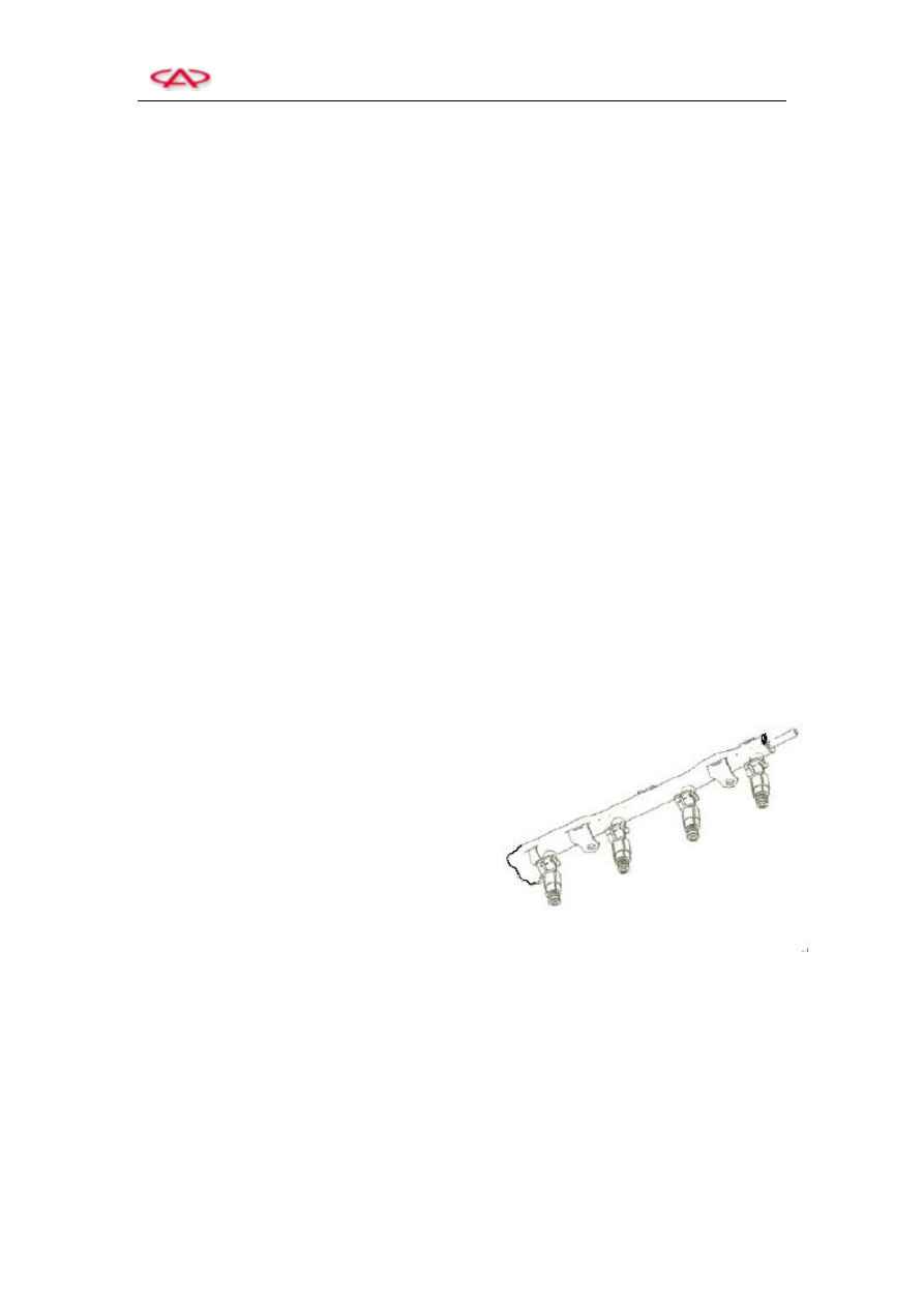
11. Steel Fuel Distributing Pipe Assy. 

Application:  It  is  used  to  store  and  distribute 

the  fuel supplied from  the fuel  pump,  provide  a 

more  stable  pressure  environment  for  the  fuel 

injection  system  to  balance  the  fuel  supply 

pressure and quantity of all cylinders and enable 

the engine to operate smoothly. 


Structure:  The  fuel  distributing  pipe  assy. 

consists  of  a  fuel  distributing  pipe  and  a  fuel 

injector. 


Installation 

Requirement: 

The 

quick 

connection  of  fuel  outlet/inlet  hose  and  fuel 

supply  pipe  must  connect  reliably.  The  vehicle 

shall  take  a  trail  run  in  situ  after  the  repair  of 

fuel  system  so  as  to  ensure  there  is  no  fuel 

leakage  in  the  fuel  system.  And,  only  this,  the 

vehicle can be delivered. 


Trouble  Diagnosis:  In  normal  condition,  the 

probability  of  the  fuel  supply  main  pipe  failure 

is very small. The failures are caused mostly due 

to the impropriate assembly that enables the fuel 

system  to  leak.  Thus,  you  shall  pay  more 

attention  to  the  following  highlights  during 

assembly:  the  used  O  oil-seal  shall  not  be 

applied again; and some lubricating  oils may be 

applied properly during assembly. 


Fuel distributing pipe assy. 


Chery T11 Service Manual                    Electric Injection System 

18 


CAUTION: 

The  pressure must  be  released  firstly  before 

the  fuel  system  is  repaired,  and  it  must  be 

ensured  that  there  is  no  pressure  oil  in  the 

fuel  pipeline.  Pull  out  the  connection  of  fuel 

pump,  and  then  put  on  the  brake  till  the 

vehicle stops. In this case, there is already no 

pressure  oil  in  this  system.  After  repair,  the 

fuel  shall  be  pumped  to  the  system  firstly 

when  the  vehicle  starts  initially,  the  method 

of  which  is:  to  turn  on  the  ignition  switch, 

and  turn  off  it  after  the  completion  of 

self-checking.  Repeat  this  procedure  3  to  4 

times. 


12. Crankshaft Position Sensor (Speed Sensor) (CKPS) 

Application:  The  crankshaft  position  sensor  is 

used  to  provide  the  ECU  with  the  engine’s 

speed,  turning  angle,  top  dead  center  signals 

which  are  applied  in  the  engine  ignition,  fuel 

injection and timing system. 


Structure  and  Principle:  The  MT  20U 

electronic  fuel  injection  system  employs  the 

magnetic  induction  coil  type  speed  sensor, 

applies  the  rotation  to  cut  the  magnetic  force 

lines  and  generate  the  alternating  current  and 

voltage  signals.  The  ECU  receives  the 

alternating  signals,  shapes  these  signals,  and 

then  changes  them  into  the  digital  signals  that 

can be identified by the ECU and applied in the 

system  control  of  engine.  The  flywheel  ring 

gear  is installed together with  the signal wheel. 

The  latter  adapts  the  58X  gear  form,  and 

provides  the  ECU  with  speed,  turning  angle, 

top  dead  center.  There  is  the  No  1  cylinder’s 

top dead center in the continuous gap. 


Profile of a crankshaft position sensor 


Chery T11 Service Manual                    Electric Injection System 

19 


Trouble Diagnosis: 

The ECU will real-time monitor the sensors and 

wires: 

1)  The sensors has no signal output; 

2)  The sensor’s output signal is distorted; 

3)  The sensor signal wire is short circuit; 

4)  The sensor signal wire is open circuit. 


Troubleshooting: 

1)  Examine the wires of  sensor,  and the  earth 

or short circuit of wire; 

2)  Apply the  three-way  instrument  to connect 

the  joints  between  the  sensor  and  harness 

and  examine  the  connection  of  power 

supply, earth wire and signal wire. 


Operating temperature: -40 to 150 

Clearance between the sensor and ring gear: 

0.3 to 1.5 mm 

Resistance of sensor: 504to 616Ω 


T11 Crankshaft Position Sensor 

Circuit diagram of crankshaft position sensor 

Pin: 

1)  No  1  (A)  for  sensor  signal  wire  high  level 

(to ECU 12#); 

2)  No  2  (B)  for  sensor  signal  wire  low  level 

(to ECU 28#); 

3)  No 3 (C) for sensor earth (to ECU 73#). 


13. Canister Control Solenoid Valve (EVAP) 

Application:  It  is  used  to  control  the  rinse  air 

flow  from  the  canister  to  the  intake  main  pipe. 

The  adsorptive  capacity  of  the  canister  is 

limited.  If  the  evaporated  gasoline  adhesive  to 

the  canister  aren’t  used  out,  the  gasoline  will 

volatilize  to  the  outside  and  pollute  the  air  as 

well as increase the insecure factors. 


Profile of a canister control solenoid valve 


Chery T11 Service Manual                    Electric Injection System 

20 


Structure  and  Principle:  There  is  a  solenoid 

valve  organization  inside  the  canister  control 

solenoid  valve.  The  digitalized  control  pulse 

square  wave  from  the  engine  will  control  the 

opening  of  the  solenoid  valve.  Based  on  the 

different operation conditions of the engine, the 

openings of the canister control solenoid valves 

are different. When the engine is operating with 

large  load  and  idle,  the  canister  control  valve 

doesn’t put into operation in order to ensure the 

output power of engine. 

Trouble Diagnosis: 

1)  The sensor-earth wires are short circuit; 

2)  The sensor-supply wires are short circuit; 

3)  The sensor wires are open circuit. 

Troubleshooting: 

1)  Examine the short or open circuit of sensor 

wires; 

2)  Examine 

the 

wire 

jumping 

among 

harnesses; 

3)  Examine  the  short  circuit  between  the 

sensor and power supply; 

4)  Examine  the  jamming  inside  the  canister 

control solenoid valve and its ventilation. 


Operating temperature: -40 to 120 

Resistance of coil: 19 to 22Ω 

Operating voltage: 8 to 16 V 

Rated operating voltage: +12V 


T11 Canister Control Solenoid Valve 

Circuit diagram of canister control solenoid 

valve 


Pin: 

1)  No 1 (A) for the solenoid valve control (to 

ECU 63#); 

2)  No  2  (B)  for  the  power  supply  of  main 

relay. 


Main Relay 


Content   ..  49  50  51  52   ..