Chery Tiggo T11 LHD. Manual - part 48


  Index      Chery     Chery Tiggo T11 LHD - service repair manual


Search            


Content   ..  46  47  48  49   ..


Chery Tiggo T11 LHD. Manual - part 48


Chery T11 Service Manual                    Electric Injection System 


3. Coolant Temperature Sensor (THW, CTS) 

Application:  This sensor  is used  to  provide the 

information  about  the  coolant’s  temperature.  It 

can  offer  an  engine’s  ECU  the  water 

temperature signal which is available  to  control 

the  startup,  idle,  ignition  timing  during  the 

normal operation, and fuel injection pulse width. 

At  the  same  time,  it  also  offers  instruments  the 

water  temperature  signal  which  is  applied  for 

the 

water 

temperature 

display 

of 

the 

instruments. The water temperature signal is the 

most  signal  for  the  cold  start  of  the  engine. 

During  the  period  of  cold  start,  the  fuel 

injection quantity  depends  on  the signal  proved 

by the water temperature sensor. 

Structure  and  Principle:  This  sensor  is  a 

thermistor with negative temperature coefficient 

(NTC),  whose  resistance  reduces as the  coolant 

temperature  rises,  and  increases  as  the  coolant 

temperature  drops,  but  it  isn’t  linear.  Based  on 

the  output  signal  from  the  sensor,  the  ECU 

monitors  the  change  of  water  temperature 

through its internal comparison circuit. 

Trouble Diagnosis:   

1)  The water temperature signal is higher than 

the limit value; 

2)  The  water  temperature  signal  is  lower  than 

the limit value; 

3)  The  open  or  short  circuits  of  the  water 

temperature sensor. 

Resistance value data at normal temperature: 

2.5±5%KΩ 

Installation Hint: The max. tightening torque is 

20 Nm. 

Hint:  This  vehicle  is  equipped  with  the 

three-wire  water  temperature  sensor.  This  kind 

of sensor features with the cost-effective and the 

system consistency. 


Profile of a coolant temperature sensor 


    T11 Water Temperature Sensor


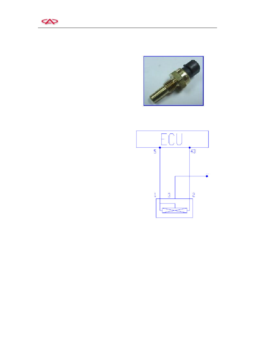
Circuit diagram of coolant temperature sensor 

Pin: 

This sensor has three pins in total, which can be 

exchanged each other. 

1)  No1  (A)  for  the  sensor  grounding  wire  (to 

Ecu 5#); 

2)  No  2  (B)  for  the  water  temperature  sensor 

signal wire (to ECU 43#); 

3)  No 2 (C) for the water temperature gauge of 

the instruments; 


To instrument 


Chery T11 Service Manual                    Electric Injection System 


The three wires of the sensor are respectively: 

a.  The 5V standard power supply wire; 

b.  The sensor signal wire (for ECU); 

c.  The 

sensor 

signal 

wire 

(for 

instruments). 

Troubleshooting:   

1)  Mainly  examine  the  short  or  open  circuit 

between  the  three  wires  on  sensor  and  the 

ECU or instruments. 

2)  Examine  the  short  or  open  circuit  and  the 

grounding among the harnesses of sensor. 

3)  Examine  the bad  wire earth  or  earth,  which 

easily  cause  the  over-high  temperature 

indicated on the water temperature gauge of 

the engine. 

Characteristic Parameters (Standard Value): 


-10 

16120Ω 

0 

9399Ω 

20 

3511Ω 

60 

671Ω 

90 

241Ω 


Operating Voltage: 5V DC 

Opening  Temperature  Range:  -40 ℃   to 

135℃ 


4. Knock Sensor (KS, KNK) 

Application:  This  sensor  is  used  to  provide  the 

ECU  with  the  knock  information  of  the  engine  to 

conduct the knock control. 

Structure  and  Principle:  The  knock  sensor  is  a 

kind  of  vibration  acceleration  sensor  mounted  on 

the  cylinder  body  of  an  engine.  It  is  generally 

installed  between  the  No  2  cylinder  and  the  No  3 

cylinder, which is in favor of the knock balance of 

the  engine.  The  ECU  utilizes  the  vibration 

frequency  signal  output  from  the  knock  sensor  to 

determine  the  knock  of  the  engine  through  the 

wave  filtering  inside  the  ECU.  When  the  knock 

signal  is  detected,  the  ECU  will  gradually  reduce 

the knock till there is no knock, and then gradually 

resume  the  knock  till  up  to  the  upper  limit  of 

knock. Repeat this procedure above. 


Profile of a knock sensor with cable 


Chery T11 Service Manual                    Electric Injection System 


Trouble  Diagnosis:  The  ECU  monitors  the 

knock  sensor,  power  amplification  circuit  and 

testing  circuit.  The  fault  flag  of  the  knock 

sensor  will  be  set  if  one  of  the  following 

conditions occurs: 

1)  The knock sensor fails; 

2)  The  knock  control  data  processing  circuit 

fails; 

3)  There are some insincere cylinder detection 

signals; 

4)  The sensor wire fails. 


After  the  fault  flag  of  the  knock  sensor  is  set, 

the closed-loop control for knocking closes and 

then  the  ignition  advance  angle  stored  in  the 

ECU  is  identified  as  a  safety  angle  by  the 

software  program.  The  fault  flag  resets  when 

the  error  frequency  drops  down  to  the  setting 

value below. 

Installation  Hint:  The  tightening  torque  is  20
±5Nm

Troubleshooting:   

1)  Mainly  examine  the  short  or  open  circuit 

between these two wires on sensor and  the 

corresponding ECU pins. 

2)  Examine  the  installation  torque  of  sensor 

and  whether  the  gaskets  are  added  when 

the sensor is installed. 

3)  Examine  the  bad  press  fit  between  the 

sensor and the cylinder body, or the foreign 

material  between  the  sensor  and  the 

cylinder body. 


T11 Knock Sensor


Circuit diagram of the knock sensor 


Pin: 

1)  No  1 (A)  for the  knock sensor signal 1  (to 

ECU 5#) 

2)  No  2 (B) for  the knock sensor signal  2  (to 

ECU 69#) 


Operating  temperature  range:  -40 ℃   to 

150 

Resistance value: > 1MΩ 


Chery T11 Service Manual                    Electric Injection System 


5. Oxygen Sensor (O

2

S) 

Application: This sensor is used to provide the 

information  about  weather  the  oxygen  is 

superfluous  after  the  fuel  injected  into  the 

engine cylinder fully combust together with air 

intake.  Based  on  these  information,  the  ECU 

can  conduct  the  fuel  quantitative  closed-loop 

control  to  convert  and  purify  three  main  toxic 

components, i.e. HC, CO and Nox  which  exist 

in  the  engine  exhaust,  with  the  help  of 

three-way catalytic converter.   

Structure and  Principle:  The  sensing  element 

of  the  oxygen sensor is a kind  of ceramic tube 

with small holes, which the outside of tube wall 

is  surrounded  by  the  engine  exhaust  while  the 

inside  is  full  of  air.  Based  on  the  oxygen 

concentration difference between the inside and 

the  outside, the sensor  indirectly figure  out the 

pulse  width  of  the  fuel  injection,  transmit  the 

width  to  the  ECU,  and  then  the  ECU  controls 

the  fuel injection  again.  At the  same time, The 

output  data  from  the  rear  oxygen  sensor  are 

detected,  and,  in  the  ECU,  the  data  from  the 

front  and  rear  oxygen  sensors  are  compared  to 

monitor  the  operation  of  three-way  catalytic 

converter. 

The  operating  voltage  of  the  oxygen  sensor 

fluctuates  at  the  range  of  0.1  to  0.9  V,  and 

changes  5  to  8  times  every  10  seconds.  If  the 

change  frequency  is  less  than  this  specified 

frequency,  it  indicates  that  the  sensor  is  aged 

which  needs to replace.  This sensor  is  difficult 

to repair. 

Trouble Diagnosis:   

The  ECU  detects the  oxygen sensor,  wires and 

the  power  amplification  circuit  and  testing 

circuit  inside  ECU.  The  fault  flag  of  oxygen 

sensor  will  be  set  if  one  of  the  following 

conditions occurs: 


Profile of a oxygen sensor 


T11 Oxygen Sensor


Circuit diagram of front oxygen sensor 

All  front  oxygen  sensors  have  the  cables.  The 

other end of a cable is the electrical connection. 

There  is  a  layer  of  asbestos  fireproof  covering 

around the outside of the sensor 


Main Relay 


Content   ..  46  47  48  49   ..