Chery Tiggo T11 LHD. Manual - part 42
T11 Service Manual Suspension and Steering
Ⅳ Removal and Installation of Rear Suspension Lower Control Arm
Assembly
Disassembly procedures:
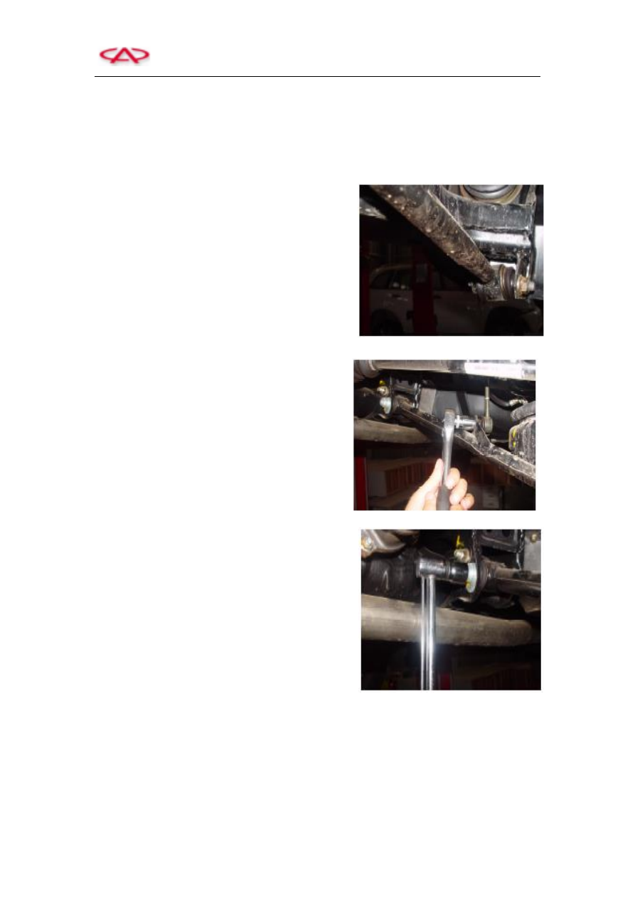
1) Unscrew the connecting bolt that joins rear
suspension lower control arm and rear towing arm.
2) Unscrew the connecting bolt that joins rear
suspension lower control arm and rear connecting
rod.
3) Unscrew the connecting bolt that joins rear
suspension lower control arm and rear subframe
welding assembly.
4) Remove the rear suspension lower control arm.
Installation procedures:
1) Refer to disassembly procedures to perform assembly.
2) Precautions:
a) Once loosening the binding bolt whose torque and angle tightening condition is controlled by
yield limit, it must be replaced.
b) After installation, torque each bolt to specification.