Chery Tiggo T11 LHD. Manual - part 37


  Index      Chery     Chery Tiggo T11 LHD - service repair manual


Search            


Content   ..  35  36  37  38   ..


Chery Tiggo T11 LHD. Manual - part 37


T11 Service Manual                        Suspension and Steering


harness bracket, then directly replace the shock absorber).     

Installation procedures 


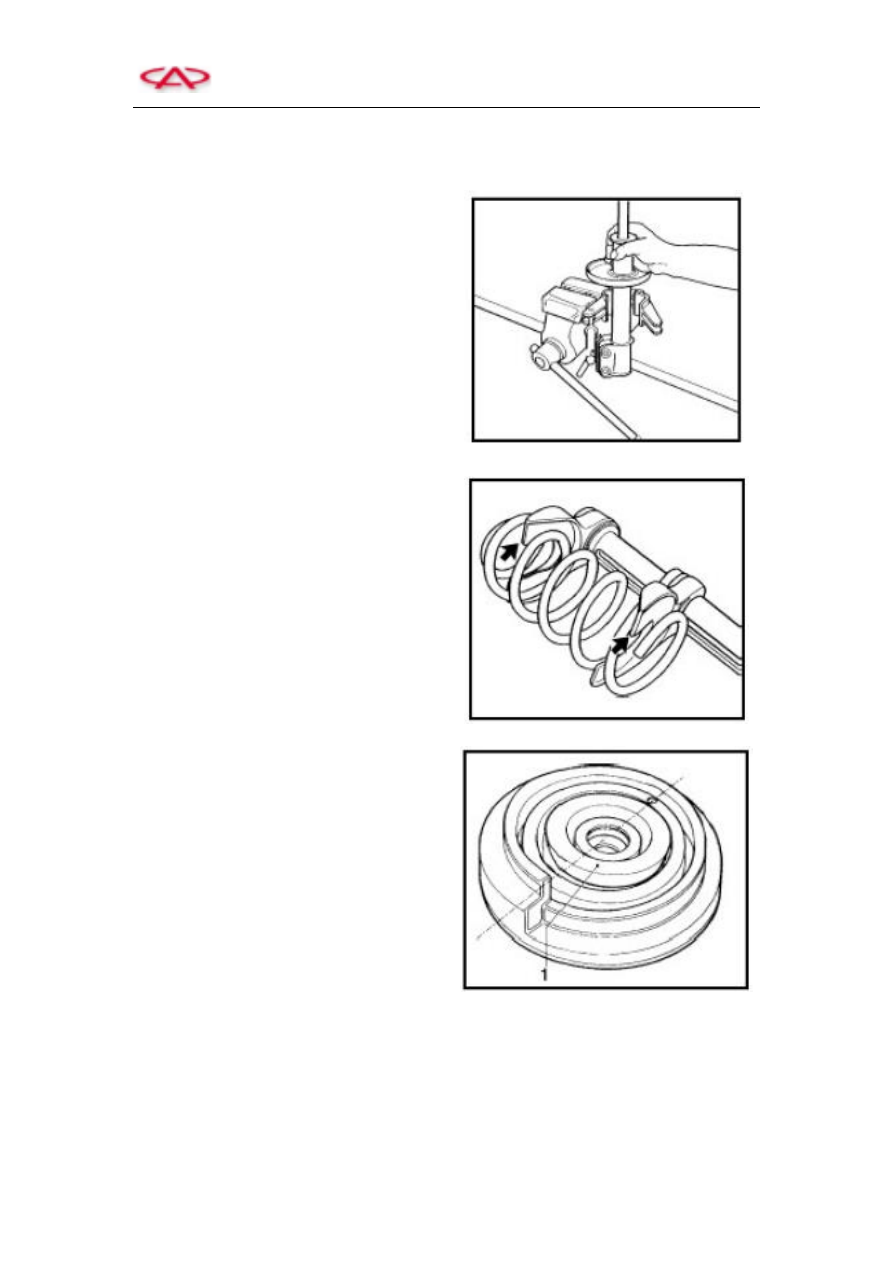
1)  Mount  the  new  shock  absorber  into  the 

assembling fixture.     

2)  If  it  is  necessary  to  replace  the  used  spring, 

loosen  the  spring,  and  then  take  out  the  used 

spring from the spring compressor.       


3)  Insert  the  new  spring  into  the  spring 

compressor, then remain one circle at the upper 

part and one and a half circles at the lower part 

of the spring (as is shown by the arrow).   


4) Compress the spring till the distance between 

the two claws is less than or equal to 120mm.     

5)  Confirm the  position  of  buffer block limiter 

1.     

6)  Fix  the  buffer  block  and  pull  the  piston  rod 

to the bottom.     


T11 Service Manual                        Suspension and Steering


7) Place the spring onto spring seat.   


Important cautions:   

The  spring  end  shall  be  located  in  the  spacing 

hole (as shown by the arrow).     


8)  Fix  the  upper  spring  seat  affixed  with 

absorber  block  to  the  position  where  the 

punched  hole  offsets  to  tightening  location  of 

lower spring bracket by 180

0

 (As shown by the 

arrow)   


9) Fix the spacer bearing and localizer.


10) Tighten it by a new lock nut.


11) Tighten the new lock nut. 


Important  cautions:  vertically  use  torque 

wrench(as shown in the figure). 


T11 Service Manual                        Suspension and Steering


Section 2 Front Axle and Front Suspension   

Ⅰ Exterior Identification   

Disassembly drawing:


——Join the control arm assembly 8 to subframe 12 with bolt 10, nut 9 and bolt 16, then torque to 

specification, and the left and right side torque shall be identical.     

——  Join  front  suspension  strut  2  to  steering  knuckle  5  by  bolt  3  and  nut  4,  then  torque  to 

specification, and the left and right side torque shall be identical.     

—— Join front suspension strut with knuckle assembly to the control arm knuckle pin by toothed 

nut  6  and  cotter  pin,  then  torque  to  specification,  and  the  left  and  right  side  torque  shall  be 

identical.     

——Respectively join the upper and lower end of front connecting rod 18 to front suspension strut 

assembly 2 and stabilizer bar 14 by nut 19, and then torque to specification, and the right and left 

torque shall be identical. 

—— Respectively join the front and the rear subframe to vehicle body by bolt 17 and bolt 4, then 

torque to specification, and the left and right side torque shall be identical.   

——Make the three studs of the front suspension strut assembly 2 go through the mounting holes 

T11 Service Manual                        Suspension and Steering


of vehicle body, then employ nut 1 to tighten them to specified torque, and the right and left side 

torque shall be identical. 

Structural Drawing of Front Axle   


Disassembly drawing: 


Left Control Arm Assembly 

Front Rubber Bushing 

Assembly 

Longitudinal Beam Welding Assembly


Front Stabilizer Bar Assembly


Right  Front  Connecting 
Rod Assembly


Rear Rubber Bushing Assembly 

Rubber Support 

Left Front Connecting Rod Assembly


Control Arm Knuckle Pin Assembly


Right Control Arm Assembly 

Subframe assembly 

Stabilizer Bar


Content   ..  35  36  37  38   ..