Chery Tiggo T11 LHD. Manual - part 25


  Index      Chery     Chery Tiggo T11 LHD - service repair manual


Search            


Content   ..  23  24  25  26   ..


Chery Tiggo T11 LHD. Manual - part 25


T11 Service Manual                                        Chassis System


Ⅵ  Brake Booster and Brake Pedal 

1. Removal of Brake Pedal and Vacuum Booster. 

1)  Unscrew  the  two  fixing  bolts  of  the  plate 

that  is  left  and  downward  to  the  instrument 

panel. 


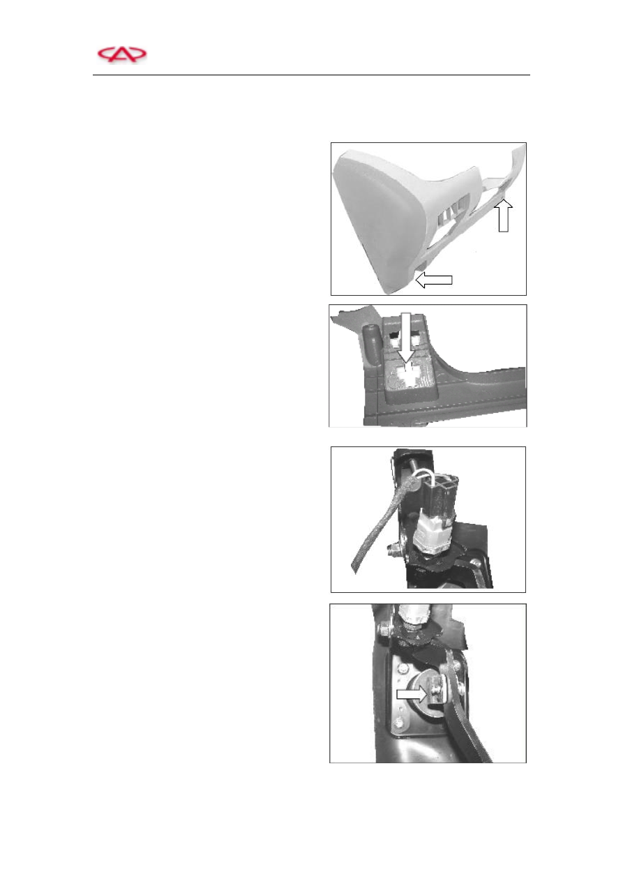
2)  Forcibly  press  and  remove  the  handle 

assembly  of  front  engine  cover  then 

disconnect  four  switch  plugs  and  finally 

remove the instrument shield. 


3)  Disconnect  the  plug  of  brake  lamp  switch 

and then remove it. 


4)  Loosen  the  connecting  pin  of  vacuum 

booster  pump  and  brake  pedal  and  then 

remove the pin. 


T11 Service Manual                                        Chassis System


5)  Unscrew the four fixing bolts of brake pedal 

bracket. 

6)  Remove the bracket of brake pedal. 


7)  Remove  the  vacuum  tube,  and  refer  to  the 

section  of  removal  of  booster  master 

cylinder to remove the vacuum booster. 

Remark:  the  interior  parts  of  booster  cannot  be 

repaired  and  the  housing  shall  not  be  split. 

Because  splitting  the  housing  may  result  in 

permanent  deformation  and  improper  boosting 

capacity. 


8)  Replacement  of  cone-way  valve of  vacuum 

booster. 

Note: the vacuum cone-way valve and seal ring 

can  be  inspected  without  demounting  the 

booster from vehicle. 

a.  Disconnect  the  vacuum  hose  of 

brake 

booster 

via 

vacuum 

cone-way valve. 

b.  Disconnect  the  vacuum  cone-way 

valve  of  brake  booster  from  the 

booster. 

c.  Remove  the  vacuum  cone-way 

valve  seal  ring  from  the  brake 

booster. 


9)  Loosen  the  adjusting  bolt  and  adjust  the 

brake pedal to specified height.     

Remark:  after  finishing  the  above  procedures, 

the  installation  procedure  of  vacuum  booster 

and brake pedal is opposite to their removal and 

mounting procedures. 


T11 Service Manual                                        Chassis System


  Installation and Removal of Brake Line   

Note: double-wall steel brake line shall be employed when replacing the brake line to avoid brake 

system malfunction. Properly layout and replace the brake line, and then fix the new brake line to 

the original location. Inadequate layout or fixing may damage the brake line, and it may result in 

poor braking effect or malfunction.     

1)  Removal  of  brake’s  master  cylinder  and 

ABS controller assembly lines.   


2)  Removal of brake line.   

a.  Loosen  the  connecting  bolt  of  ABS 

hydraulic unit.     


b.  Remove  the  fixing  clip  of  vehicle 

body  and  the  fixing  bolts  of  brake 

line.   


Connecting  Line 
of 

the 

First 

Piston 

of 

the 

Master Cylinder 

Front  Right  Brake 

Connecting Line


Front  Left  Brake 

Connecting Line


T11 Service Manual                                        Chassis System


3)  Removal of brake hose   

a.  Lift the vehicle to remove the tires.     

b.  Employ  sustaining  spanner  to  clamp 

the  hose  coupling,  and  then  remove 

the  brake  line  from  the  brake  hose 

bracket.  Please  never  bend  or  break 

the brake pipeline or bracket.   

c.  Remove  the  clip  of  clamp  holder  on 

the hose assembly bracket.   

d.  Remove the hose from the bracket.     


4)  Remove  the  following  parts  from  caliper: 

brake  hose  bolt,  hose,  and  two  washers 

(Remark:  They  shall  be  replaced  when 

installing).   


Caution:  prior  to  achieving  reliable  brake  pedal  travel,  never  move  the  vehicle.  And  air  in  the 

brake line may result in poor braking effect or brake malfunction.     

Remark: never suspends parts onto brake flexible hose, because this may damage the hose. Never 

bend or break any section of the brake hose to avoid brake fluid leakage from any parts.     

Remark: brake lines shall not disturb vehicle body.     

Tightening torque of brake joint bolts shall be as below:     

M12×1: 16~20N.m   

M11×1.5: 13~17N.m   

M10×1: 10~14N.m   


Content   ..  23  24  25  26   ..