Chery Tiggo T11 LHD. Manual - part 20


  Index      Chery     Chery Tiggo T11 LHD - service repair manual


Search            


Content   ..  18  19  20  21   ..


Chery Tiggo T11 LHD. Manual - part 20


T11 Service Manual                                        Chassis System


□  Deflection driving 
□  Abnormal performance 

Maintain  brake surface precision  can prolong  the service life of lining.  Brake disc  slight scratch 

whose  depth is less than 1.5mm  will not influence braking performance, as  normal  use can also 

result in slight scratch. 


6. Replacement of Brake Caliper 

1) Removal procedures 

Caution:  prior  to  achieving  stable  brake  pedal  stroke,  never  move  the  vehicle  to  prevent  from 

personal injury! 

a.  Discharge a small amount of brake fluid from master cylinder. 

b.  Lift and properly sustain the vehicle. 

c.  Mark the relative locations of wheel and hub. 

d.  Refer to tire and wheel removal and installation to remove the front tire and wheel assembly.   

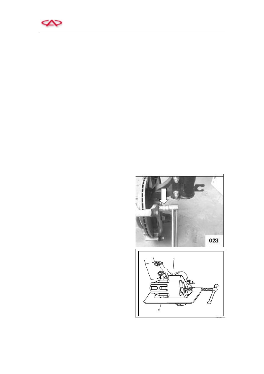
e.  Unscrew the fixing bolt of brake caliper 


f.  Fix  a  large  C-shape  clamp  2  onto  the  top 

of brake caliper, and press it to the back of 

external brake lining. 


g.  Tighten the C-shape clamp till the caliper piston is pushed to an adequate depth in the caliper 

cylinder sleeve so as to make the brake caliper slide out of the brake disc. 

h.  Remove the fixed bracket of the lining thickness sensor harness. 

T11 Service Manual                                        Chassis System


i. 

Refer to the replacement of brake lining. 

j. 

Remove the dust cover of oil cylinder. 


Remove  dust  cover  from  oil  cylinder  by 

screwdriver. 


k.  Remove the piston   

(a)  Use a piece of wood board to stop the 

piston, put the board between pistons, 

and  then  insert  the  lining  from  one 

side.     

(b)  Use  compressed  air  to  carefully 

squeeze out the piston through switch 

port.  Put  a  shield  (for  example, 

hardwood)  at  the  notch  of  brake 

caliper  to  protect  the  piston.    Never 

hold  the  piston  by  finger,  as  it  is  too 

dangerous! 


l. 

Inspect the guide sleeve (5)     


When manually push the guide sleeve, it must 

be  smooth.  If  stagnation  or  heaviness  occurs, 

please replace the guide sleeve   

Note:  Grease  shall  be  applied  to  the  guide 

sleeve when assembling.   


m.  Remove  the  seal  ring  via  plastic  pin 

carefully.  Use  alcohol  to  clean  the  brake 

cylinder  and  parts,  and  apply  compressed 

air  to  blow  it  dry.  Check  through  the 

surface  of  brake  cylinder,  piston  and 

flange.  Never  carry  out  mechanical 

machining to brake cylinder and piston.     


T11 Service Manual                                        Chassis System


2) Installation   

a.  Bray brake cylinder grease on the cylinder, 

stud plug and seal sleeve, and then fix seal 

ring  in  the  ring  slot  at  the  tail  of  brake 

cylinder.    Finally  fix  the  dust  seal  ring 

into  the  front  ring  slot  and  press  the 

overall seal ring into the ring slot.     


b.  The area between dust seal ring and brake 

caliper  house  must  be  kept  dry.    Never 

contact  brake  cylinder  grease  or  brake 

fluid  to  ensure  the  dust  seal  ring  properly 

located. 


c.  Use  extended  piece  sold  in  the  market  to 

fix  the  brake  piston  and  gently  press  it 

onto  dust  seal  ring,  and  then  blow  dust 

ring  via  compressed  air  (maximum  3bar). 

Finally fix  the sealing ring  over the brake 

piston. 


d.  Use  brake  fluid  to  soak  the  dust  seal  ring  and  brake  piston  to  enable  the  seal  ring  to  past 

through the piston easily. 


7. Inspection and Replacement of Brake Lining 

For all of the Chery vehicles, genuine brake linings shall be used for replacement to prevent from 

affecting braking performance. 


T11 Service Manual                                        Chassis System


  Removal   

1)  Lift  and  properly  sustain  the  vehicle  to 

remove trim board.   


Note:  prevent  the  front  surface  of  the  trim 

board from scraping ground after dismounting 

the trim board.     


2)  Unscrew the five fixing bolts of the wheel 

and then remove the wheel.   


Torque: 120N.m   

Note:  The  tightening  torque  of  tire  bolt  shall 

be highlighted.   


3)  Unscrew  the  fixing bolt  of  the  harness  of 

the  lining  wearing  indication  lamp,  and 

then  pull  out  the  plug  of  lining  thickness 

warning  lamp.    (Remark:  the  plug  of 

lining thickness warning lamp is a kind of 

preset one.)   


4)  Loosen the guide bolt above brake caliper 

(a),  and  then  loosen  the  guide  bolt  below 

brake  caliper.    And  finally  take  out  the 

brake  caliper.    Never  connect  brake 

caliper  with  brake  hose  to  prevent  from 

brake hose damage. 


Installation instructions:   

Only  clean  the  guide  bolt,  but  never  apply 

grease to the guide bolt. 


(a) 


Content   ..  18  19  20  21   ..