Chery Tiggo. Manual - part 414


  Index      Chery     Chery Tiggo - service repair manual 2009 year


Search            


Content   ..  412  413  414  415   ..


Chery Tiggo. Manual - part 414


Diagnostic Procedure

1.

CHECK GROUND CONNECTION

• Turn ignition switch off.

• Loosen and retighten ground screws on the body (See Ground Inspection in Section 15 Body & Accessories).

• Inspect ground connection C-201 mounting position (See Vehicle Wiring Harness Information - Main Harness in

Section 16 Wiring).

Is the ground connection OK?

Yes

>>

Go to the next step.

No

>>

Repair or replace ground harness or connections.

2.

CHECK INSTRUMENT CLUSTER (IC) ELECTRICAL CONNECTOR

• Disconnect Instrument Cluster (IC) electrical connector.

• Inspect the electrical connector for damage.

Is the electrical connector OK?

Yes

>>

Go to the next step.

No

>>

Repair or replace the electrical connector as necessary.

3.

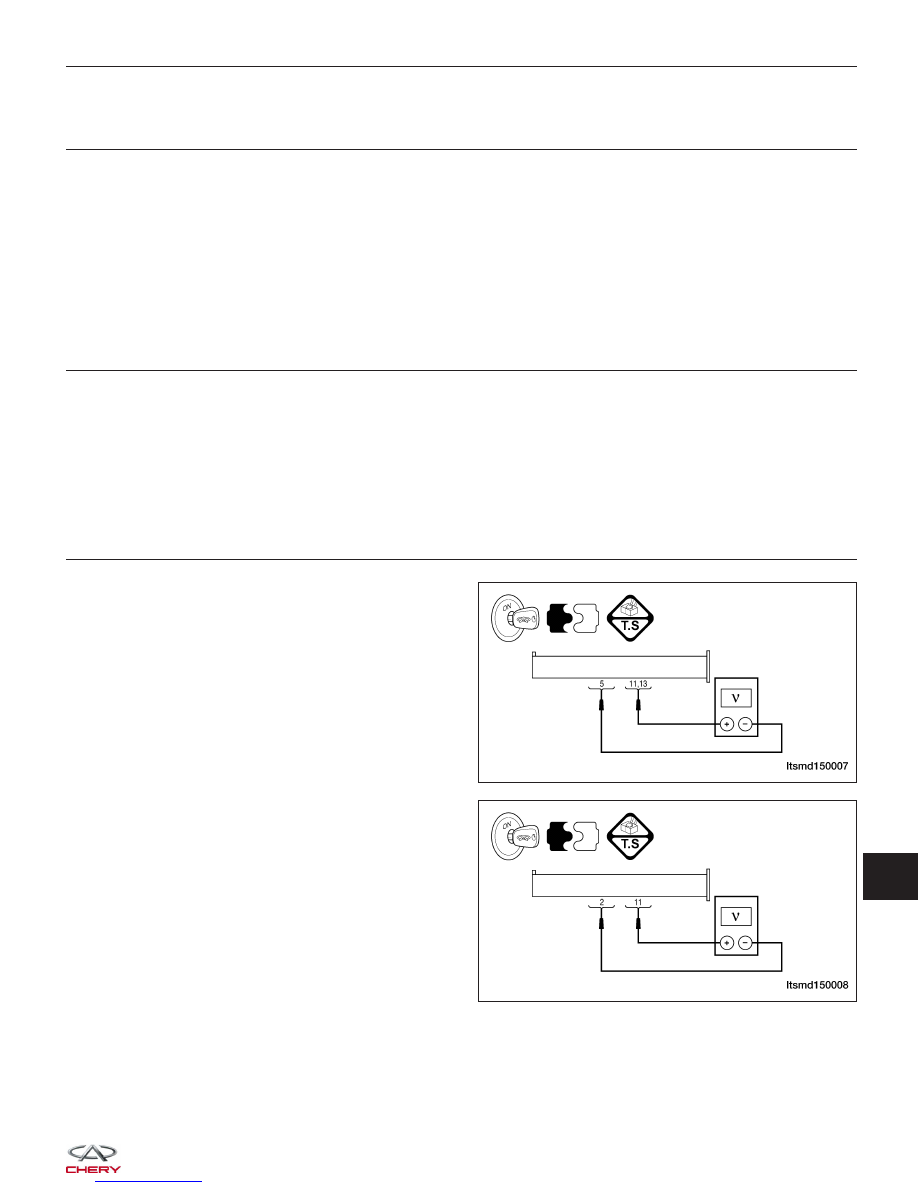
CHECK INSTRUMENT CLUSTER (IC) POWER SUPPLY

• Turn ignition switch on.

• If the vehicle is not equipped with Mitsubishi 2.4L

engine system, check IC power supply between
terminal 11, 13 and terminal 5 in the IC electrical
connector C-001 terminal side.

• If the vehicle is equipped with Mitsubishi 2.4L

engine system, check IC power supply between
terminal 11 and terminal 2 in the IC electrical con-
nector C-001 terminal side.

Is the voltage between 9 - 17 V?

Yes

>>

Replace the IC.

No

>>

Go to the next step.

DIAGNOSIS & TESTING

LTSMD150007

LTSMD150008

15


4.

CHECK SYSTEM VOLTAGE

• Start the engine, raise the speed over 1000 RPM.

• Measure the charging voltage with the voltmeter at the battery positive and negative terminals.

Is the voltage less than 9 V?

Yes

>>

Check the charging system.

No

>>

Go to the next step.

5.

CHECK THE BATTERY

• Start the engine, raise the speed over 1000 RPM for a few minutes.

• Turn ignition switch off.

• Measure the voltage drop with the voltmeter at the battery positive and negative terminals while cranking the

engine.

• Battery voltage should be more than approximate 9 V.

Is the check result normal?

Yes

>>

Go to the next step.

No

>>

Charge or replace the battery.

6.

CHECK INSTRUMENT CLUSTER (IC) SUPPLY CIRCUIT

• Disconnect the battery negative cable.

• Disconnect the battery positive cable.

• Measure the resistance between IC terminal 11, 13 and battery positive cable.

• Continuity should exist.

Is the check result normal?

Yes

>>

Go to the next step.

No

>>

Check fuse.
Check the harness open or short to ground.
Check related components.

7.

CHECK SYSTEM VOLTAGE

• Start the engine, raise the speed over 1000 RPM.

• Measure the charging voltage with the voltmeter at the battery positive and negative terminals.

Is the voltage more than 17 V?

Yes

>>

Replace the AC generator.

No

>>

Go to the next step.

DIAGNOSIS & TESTING


8.

CHECK DTC

• With the X-431 scan tool, read IC DTCs.

• Refer to ⬙DTC Confirmation Procedure⬙.

Is the DTC U029C still present?

Yes

>>

Replace IC.

No

>>

The system is now operating properly.
Reassemble the vehicle and verify the customers complaint is repaired.

DIAGNOSIS & TESTING

15


U040F - Temperature Sensor Shorted To Supply
U040F - Temperature Sensor Shorted To Ground (With Mitsubishi 2.4L Engine
System)

Instrument Cluster (IC)

DIAGNOSIS & TESTING

LTSMW150039T


Content   ..  412  413  414  415   ..