Chery Tiggo. Manual - part 412


  Index      Chery     Chery Tiggo - service repair manual 2009 year


Search            


Content   ..  410  411  412  413   ..


Chery Tiggo. Manual - part 412


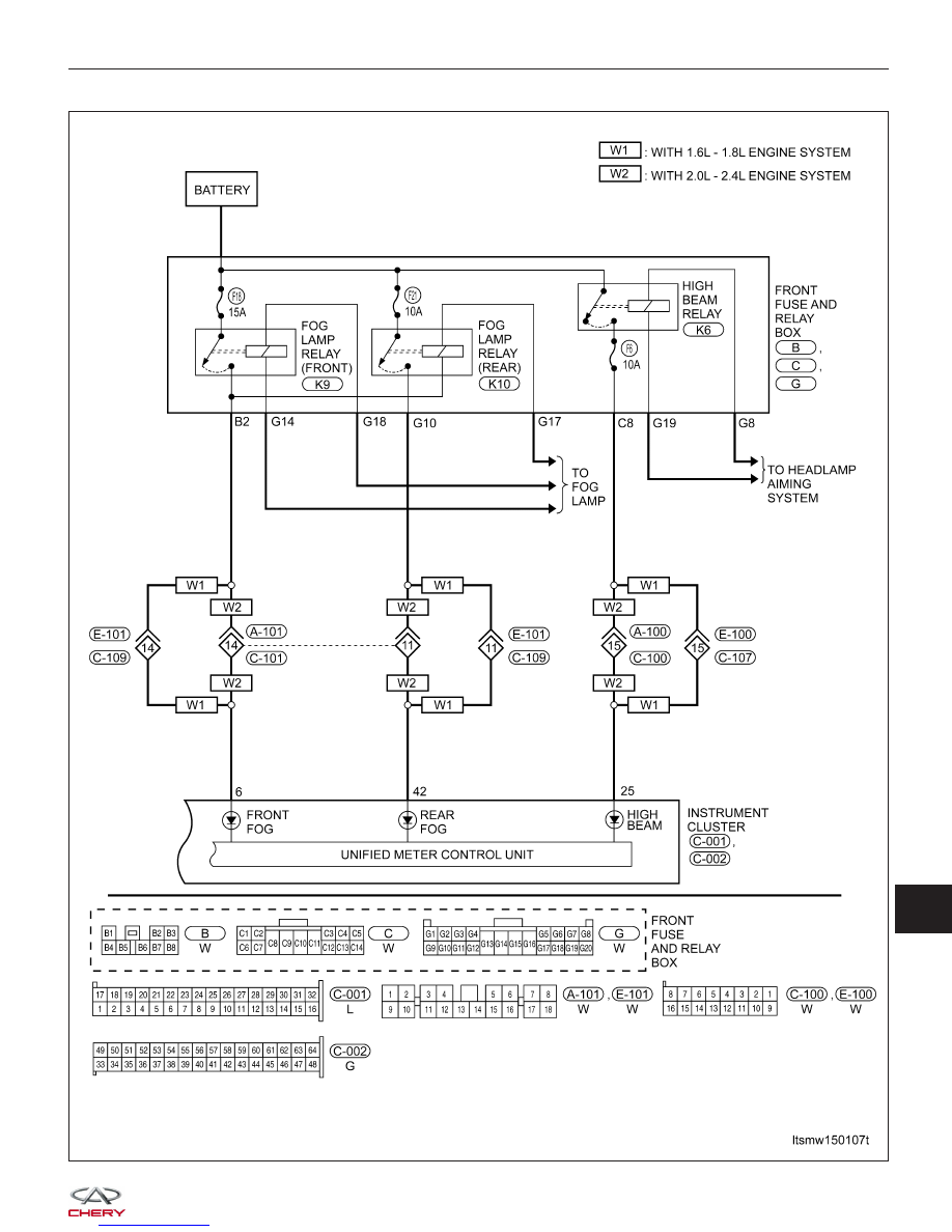
Instrument Cluster (Page 8 of 8)

INSTRUMENT CLUSTER

LTSMW150107T

15


Instrument Cluster Connector Pin-Out Table

Instrument Cluster Connector Pin-Out Table

PIN

CIRCUIT IDENTIFICATION

PIN

CIRCUIT IDENTIFICATION

1

Door Lamp

33

N/A (With ACTECO Engine)

P (With MITSUBISHI Engine)

2

N/A (With ACTECO Engine)

34

N/A (With ACTECO Engine)

GND (With MITSUBISHI Engine)

R (With MITSUBISHI Engine)

3

GND (Power)

35

N/A (With ACTECO Engine)

N (With MITSUBISHI Engine)

4

PWM Gear Mode

36

N/A (With ACTECO Engine)

Auto Mode (With MITSUBISHI Engine)

5

GND (Sensor)

37

N/A (With ACTECO Engine)

4 (With MITSUBISHI Engine)

6

Front Fog Lamp

38

N/A (With ACTECO Engine)

3 (With MITSUBISHI Engine)

7

39

N/A (With ACTECO Engine)

2 (With MITSUBISHI Engine)

8

Cruise Lamp

40

N/A (With ACTECO Engine)

1 (With MITSUBISHI Engine)

9

Low Oil Pressure Lamp

41

10

Speed Input

42

Rear Fog Lamp

11

Continuous Supply Voltage

43

12

Illumination Lamp

44

13

Ignition Switch

45

14

ABS Lamp

46

15

Diagnostic Link K

47

Sport Mode (With ACTECO Engine)

N/A (With MITSUBISHI Engine)

16

Charge Lamp

48

Winter Mode (With ACTECO Engine)

N/A (With MITSUBISHI Engine)

17

Airbag Lamp

49

TCM Failure (With ACTECO Engine)

N/A (With MITSUBISHI Engine)

18

Parking Brake Lamp

50

19

Seatbelt Lamp

51

20

MIL Lamp

52

21

Low Fuel Level Lamp

53

22

Left Turn Lamp

54

23

Coolant Temperature Input

55

24

Right Turn Lamp

56

25

High Beam Lamp

57

26

Low Brake Fluid Level Lamp

58

27

Vehicle Speed Input

59

28

Parking Lamp

60

29

EPC Lamp

61

INSTRUMENT CLUSTER


PIN

CIRCUIT IDENTIFICATION

PIN

CIRCUIT IDENTIFICATION

30

62

31

Fuel Consumption Input

63

32

64

INSTRUMENT CLUSTER

15


DIAGNOSIS & TESTING

Clearing Service Monitor Lamp

Perform the following to clear the service monitor lamp:

1. Turn the ignition switch off.

2. Press down and hold the Mode switch.

3. Turn the ignition switch on.

4. Release the Mode switch.

5. Press the Mode switch and the Clock switch simultaneously within 30 seconds and hold less than 2 seconds to

clear the mileage maintenance identification.

Diagnostic Help

1. The X-431 scan tool connects to the Data Link Connector (DLC) and communicates with the vehicle electronic

modules through the class two serial data circuit.

2. Confirm that the malfunction is current and carry-out the diagnostic tests and repair procedures.

3. If the DTC cannot be deleted, it is a current fault.

4. Use a digital multimeter to perform voltage readings on electronic systems.

5. Refer to any Technical Bulletins that issued.

6. Visually inspect the related electrical wiring harness.

7. Inspect and clean all Instrument Cluster (IC) grounds that are related to the DTC.

8. If numerous trouble codes were set, use the electrical schematic and look for any common ground circuits or

voltage supply circuits that may apply to the DTC.

Intermittent DTC Troubleshooting

If the failure is intermittent, perform the following:

• Check for loose connectors.

• Look for any chafed, pierced, pinched, or partially broken wires.

• Monitor the scan tool data relative to this circuit.

• Wiggle the related electrical wiring harness and connectors while looking for an interrupted signal on the

affected circuit.

• If possible, try to duplicate the conditions under which the DTC set.

• Look for the data to change or for the DTC to reset during the wiggle test.

• Look for broken, bent, pushed out or corroded terminals.

• Inspect the sensor and mounting area for any condition that would result in an incorrect signal, such as dam-

age or foreign material.

• A data recorder, and/or oscilloscope should be used to help diagnose intermittent conditions.

Ground Inspection

Ground connections are very important to the proper operation of electrical and electronic circuits. Ground connec-
tions are often exposed to moisture, dirt and other corrosive elements. The corrosion (rust) can become an unwanted
resistance. This added resistance can alter the way a circuit works.

Electronically controlled circuits are very sensitive to proper grounding. A loose or corroded ground can drastically
affect an electronically controlled circuit. A poor or corroded ground can effect the circuit. Perform the following when
inspecting a ground connection:

1. Remove the ground bolt or screw.

2. Inspect all mating surface for tarnish, dirt, rust, etc.

3. Clean as required to assure good contact.

4. Reinstall bolt or screw securely.

5. Inspect for

⬙add-on⬙ accessories which may be interfering with the ground circuit.

6. If several wires are crimped into one ground eyelet terminal, check for proper crimps. Make sure all of the wires

are clean, securely fastened and providing a good ground path. If multiple wires are crimped to one eyelet, make
sure no excess wire insulation has been crimped creating a bad ground.


Content   ..  410  411  412  413   ..