Chery Tiggo. Manual - part 328


  Index      Chery     Chery Tiggo - service repair manual 2009 year


Search            


Content   ..  326  327  328  329   ..


Chery Tiggo. Manual - part 328


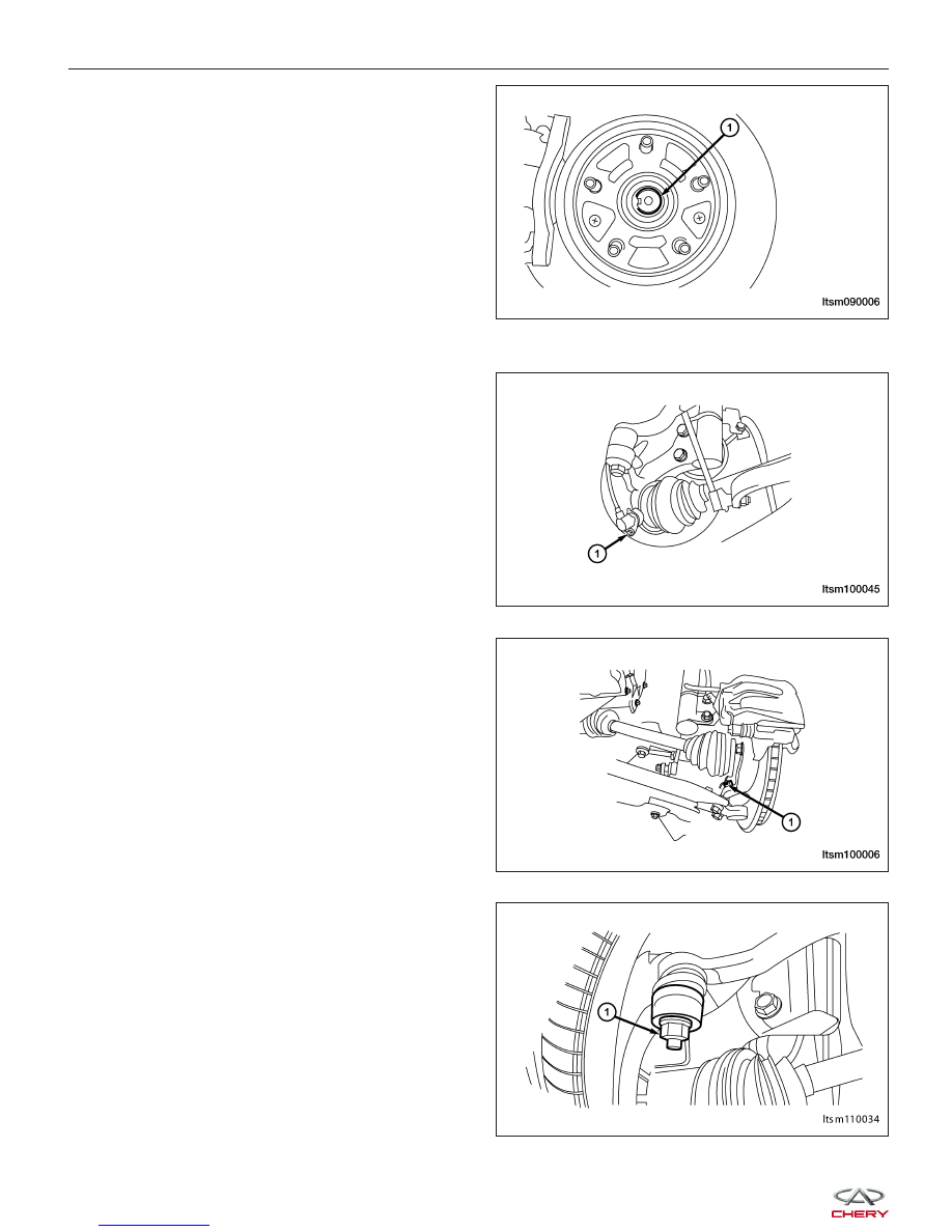
4. While a helper applies the brakes to keep the hub

from rotating, remove the front axle shaft nut (1).
(Tighten: Front axle shaft nut to 135 N·m)

5. Access and remove the front brake rotor (See Front Brake Rotor Remove & Installation in Section 12 Brakes).

6. Remove the wheel speed sensor mounting bolt (1).

(Tighten: Wheel speed sensor mounting bolt to 10
± 1 N·m)

7. Remove the wheel speed sensor and set it aside.

8. Remove the lower ball joint mounting nut (1)

attaching the lower control arm to the knuckle.
(Tighten: Control arm to steering knuckle nut to
120 ± 10 N·m)

9. Remove the nut (1) attaching the outer tie rod end

to the steering knuckle.
(Tighten: Outer tie rod end nut to 32 - 38 N·m)

ON-VEHICLE SERVICE

LTSM090006

LTSM100045

LTSM100006

LTSM110034


10. Using special tool CH-10002, remove the outer tie

rod end from the steering knuckle.

11. While holding the bolt heads stationary, remove the

two nuts (1) from the bolts attaching the strut to the
knuckle.
(Tighten: Strut to the knuckle nuts to 135 N·m)

NOTE :
Do not allow the half shaft to hang by the inner C/V joint. It must be supported to keep the joint from separating
during this operation.

12. Pull the knuckle off the half shaft outer C/V joint splines and remove the knuckle from the vehicle.

13. If required, remove the screws fastening the shield to the knuckle.

14. If required, use a suitable tool to press the hub and bearing out of the knuckle.

15. Installation is in the reverse order of removal.

Installation Notes:
• After installing the front steering knuckle, perform a front end alignment (See Front Wheel Alignment in Section

10 Suspension).

Front Lower Control Arm

Description

The lower control arm is located between the steering knuckle and the vehicle sub-frame. The lower control arm uses
a lower ball joint on the outer end and two sub-frame mounts on the inner end.

Operation

The front lower control arm supports the steering knuckle. The lower control arm controls the vehicle steering by
maintaining the proper wheel alignment through all driving conditions.

Removal & Installation

NOTE :
Inspect the lower control arm for signs of damage from contact with the ground or road debris. If the lower control
arm shows any sign of damage, look for distortion. Do not attempt to repair or straighten a broken or bent lower
control arm. If damaged, the lower control arm is serviced only as a complete component.

ON-VEHICLE SERVICE

LTSM110027

LTSM100041

10


1. Raise and support the vehicle.

2. Remove the wheel mounting nuts and the wheel assembly.

(Tighten: Wheel mounting nuts to 110 N·m)

3. Remove the bolt (1) between the control arm and

the sub-frame.
(Tighten:

Control

arm

to

sub-frame

bolt

to

180 ± 10 N·m)

4. Remove the nut (1) between the control arm and

the steering knuckle.
(Tighten: Control arm to steering knuckle nut to
120 ± 10 N·m)

5. Remove the bolt (1) between the rear rubber

sleeve of the control arm and the sub-frame.
(Tighten: Rear rubber sleeve control arm to sub-
frame bolt to 180 ± 10 N·m)

6. Remove the control arm from the vehicle.

7. Perform the following inspection procedure before installation.

ON-VEHICLE SERVICE

LTSM100055

LTSM100006

LTSM100057


Inspection

Lower control arm inspection:

a. Check for smooth rotation.

b. Inspect ball stud for damage.

c. Inspect dust cover for damage or oil leak.

d. Inspect for play in the ball joint, if defective,

           replace the ball joint.

8. Installation is in the reverse order of removal.

Installation Notes:
• After installation, each bolt must be tightened to the required tightening torque.

Front Stabilizer Bar Link

Removal & Installation

1. Raise and support the vehicle.

2. Remove the wheel mounting nuts and the wheel assembly.

(Tighten: Wheel mounting nuts to 110 N·m)

3. Remove the nut (1) between the front stabilizer link

and the mounting bracket on the front strut.
(Tighten: Front stabilizer link and the mounting
bracket nut to 48 ± 6 N·m)

4. Remove the nut (1) between the front stabilizer bar

link and the front stabilizer bar.
(Tighten: Front stabilizer link and the front stabilizer
bar nut to 48 ± 6 N·m)

5. Installation is in the reverse order of removal.

ON-VEHICLE SERVICE

PZSM100031

LTSM100010

LTSM100046

10


Content   ..  326  327  328  329   ..