Chery Tiggo. Manual - part 326


  Index      Chery     Chery Tiggo - service repair manual 2009 year


Search            


Content   ..  324  325  326  327   ..


Chery Tiggo. Manual - part 326


ON-VEHICLE SERVICE

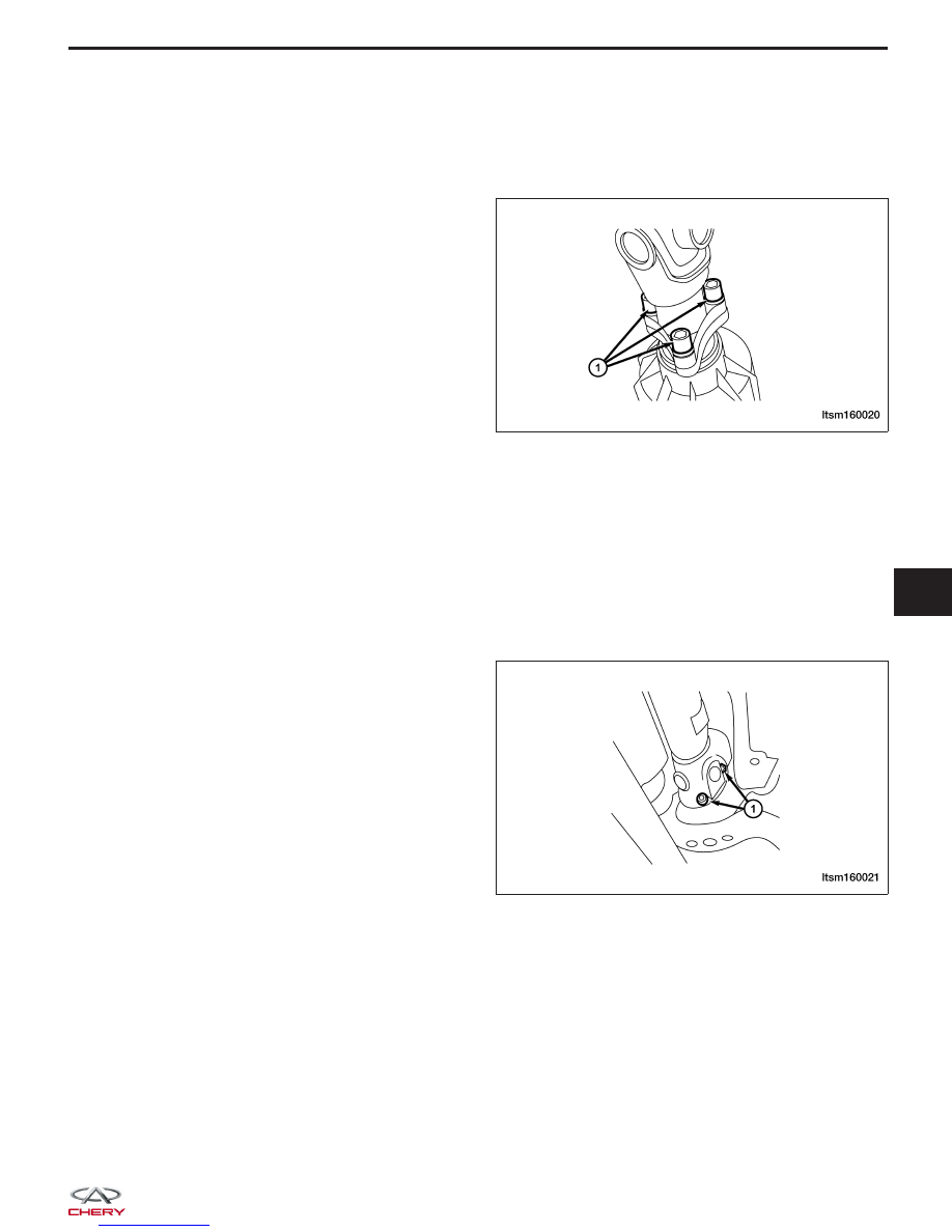
Front Intermediate Drive Shaft

Removal & Installation

1. Remove the bolts (1) between the front intermedi-

ate drive shaft and the ITM Controller input shaft.
(Tighten: Front intermediate drive shaft and ITM
controller bolts to 70 ± 7 N·m)

2. Installation is in the reverse order of removal.

Rear Intermediate Drive Shaft

Removal & Installation

1. Remove the bolts between the rear intermediate drive shaft and the ITM Controller output shaft.

(Tighten: Rear intermediate drive shaft and ITM controller bolts to 39 ± 3 N·m)

2. Remove the bolts between the intermediate drive shaft bracket and the vehicle body, and then remove the

bracket.
(Tighten: Rear intermediate drive shaft to body bolts to 60 ± 5 N·m)

3. Remove the bolts (1) between the rear intermedi-

ate drive shaft and the rear axle flange, and
remove the rear intermediate drive shaft.
(Tighten: Rear intermediate drive shaft and rear
axle flange bolts to 65 ± 6 N·m)

4. Installation is in the reverse order of removal.

LTSM160020

LTSM160021

09


SUSPENSION

10

CONTENTS

page

Front Suspension . . . . . . . . . . . . . . . . . . . . . . . . . . . . . . . . . . . . . . . . . . . . . . . . . . . . . . . . . . . . . . . . . . . . . 10-1

Rear Suspension . . . . . . . . . . . . . . . . . . . . . . . . . . . . . . . . . . . . . . . . . . . . . . . . . . . . . . . . . . . . . . . . . . . . 10-25

Alignment . . . . . . . . . . . . . . . . . . . . . . . . . . . . . . . . . . . . . . . . . . . . . . . . . . . . . . . . . . . . . . . . . . . . . . . . . . 10-38

Wheels and Tires . . . . . . . . . . . . . . . . . . . . . . . . . . . . . . . . . . . . . . . . . . . . . . . . . . . . . . . . . . . . . . . . . . . 10-47

FRONT SUSPENSION

GENERAL INFORMATION

10-2

Description

10-2

Operation

10-4

Specifications

10-4

Special Tools

10-5

DIAGNOSIS & TESTING

10-6

Vehicle Suspension Troubleshooting Chart

10-6

ON-VEHICLE SERVICE

10-7

Front Steering Knuckle

10-7

Description

10-7

Operation

10-7

Removal & Installation

10-7

Front Lower Control Arm

10-9

Description

10-9

Operation

10-9

Removal & Installation

10-9

Front Stabilizer Bar Link

10-11

Removal & Installation

10-11

Front Stabilizer Bar

10-12

Removal & Installation

10-12

Front Strut Assembly

10-13

Description

10-13

Operation

10-14

Diagnosis & Testing

10-14

Removal & Installation

10-14

Front Coil Spring

10-16

Description

10-16

Operation

10-16

Removal & Installation

10-16

Front Sub-Frame Assembly

10-17

Removal & Installation

10-17

UNIT REPAIR

10-21

Front Strut

10-21

Disassemble

10-21

Inspection

10-22

Strut Disposal Procedure

10-22

Assembly

10-23

10


GENERAL INFORMATION

Description

The front suspension system incorporates a strut assembly that takes the place of the upper control arm and upper
ball joint. The strut carries out the function of a shock absorber and is encompassed by a coil spring. The strut
assembly supports the weight of the vehicle and is also the pivot point for the steering knuckle. This system uses a
lower control arm and ball joint for the lower pivot point of the steering knuckle.


The front suspension consists of the following components:

GENERAL INFORMATION

LTSM100008

10


Content   ..  324  325  326  327   ..